[This is Part 2 of this post; click here for the first part.]
OpenSCAD is an open-source (completely free) 3D solid CAD program; it works on Windows, Linux, and Mac OS X.
It calls itself “The Programmers Solid 3D CAD Modeller”, and indeed that’s what makes it special.
Unlike any other CAD system I’ve seen, OpenSCAD is driven entirely by a program-like script. That sounds like it would be a lot harder to use than a GUI-based CAD system – but it’s not! It’s much easier to use, with a much shorter learning curve. The scripts use a C-like syntax that will be instantly familiar to anyone who’s worked even a little with C or a C-derived braces-and-semicolon language (C++, Java, C#, etc.).
In 15 minutes with OpenSCAD, I was able to do far more than I could with AutoCAD or SketchUp after several hours – with a lot less frustration. If you have any background in programming at all, you’ll find it ridiculously easy to learn and use.
OpenSCAD has a simple but effective IDE, so you can try things interactively at the keyboard – just type some commands, mash F5, and see the result instantly. Once your 3D model is rendered, you can use the IDE to zoom in and out and look at your model from any angle.
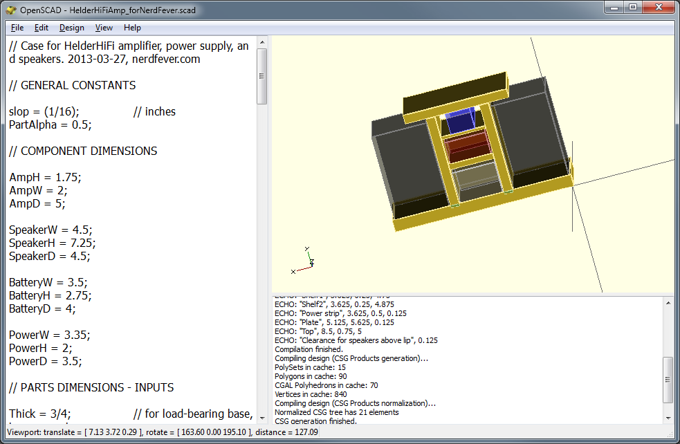
OpenSCAD showing my modeled speaker set
What makes OpenSCAD great for engineering drawings is it’s ability to position and size things numerically – if you want a part exactly 3.75 inches to the left of another part, just subtract 3.75 from the x-coordinate of the part, and that’s where it will be. If you want a part to be tall enough to cover 9 other parts, just get the dimensions of the other parts, add them up (in your script) and feed the result in as the height value.
That way, if you resize one part of your model, all the other parts that depend on it for their own size and position automatically get adjusted to compensate. If you want something centered with respect to some dimension, just take the dimension and divide it by 2 to get the proper position!
None of this is “magic” performed by OpenSCAD – this is stuff done by you, in your own script (program), so it’s 100% under your control.
For example:
cube([w, h, d]);
Gives you a rectangular prism with the given width, height and depth. “w”, “h”, and “d” can be literals – so cube([1,4,9]); gives you a 2001-type monolith. Or they can be program variables, which you can pass to a module and whose values you can compute.
There are commands to translate, mirror, and rotate objects (or groups of objects), and you can assign colors and transparency to them (but not textures, yet anyway). All the basic arithmetic and trigonometry functions are there to help you compute sizes, positions, and angles. And you can construct objects by any combination of adding or subtracting primitives (rectangular prisms, cylinders, spheres, and polyhedrons).
Conditionals and iteration are available with C-like “if” and “for” statements, so you can write a “real program”.
One unexpected thing is that the compiler is somewhat primitive – all variable values are computed at compile time (not “run time”); this has to be kept in mind when writing scripts, but I didn’t find it a serious problem.
The OpenSCAD website has an excellent manual (by freeware standards) that explains all this, as well as a handy “cheat sheet” for quick reference.
So far, I’ve used OpenSCAD only for this one project, and that took just a few hours – most of the time was spent tweaking the design of my speaker case. (Unlike all the other CAD programs I tried, hardly any time was spent figuring out how the program works.)
However, I quickly found a few tricks worth mentioning:
module part(name, w, h, d) {
cube ([w, h, d]);
echo (name, w, h, d);
}
This defines a module (something like a function) called “part”, which I use to define each separate part I’ll have to cut out of plywood to assemble the speaker set. Each part has a name, width, height and depth, and when the part is rendered, it prints out (via the “echo” statement) the name and dimensions, so I get a automatically-generated “cut list” of parts to make.
For example, I have this code:
module base(x,y,z) { translate([x,y,z]) { part(“Base”, BaseW, BaseH, BaseD); } }
This defines a module “base” that will create the base of the speaker case, using the dimensions in the variables BaseW, BaseH, and BaseD. The x, y, z inputs to the module give the position where the base should be.
Later in my script, I call:
base(0,0,0);
Which creates the base of the speaker set, positioned at the origin of my coordinate space. It also prints the output:
ECHO: “Base”, 14.375, 0.75, 4.75
Which gives me the dimensions I need to cut to make the base. (The print formatting abilities of the script language are minimal, but adequate for this purpose.)
Here is the first part of my final script – it gives you an idea of how I calculated the dimensions of parts:
// Case for HelderHiFi amplifier, power supply, and speakers. 2013-03-27, nerdfever.com
// GENERAL CONSTANTS
slop = (1/16); // inches
PartAlpha = 0.5;// COMPONENT DIMENSIONS
AmpH = 1.75;
AmpW = 2;
AmpD = 5;SpeakerW = 4.5;
SpeakerH = 7.25;
SpeakerD = 4.5;BatteryW = 3.5;
BatteryH = 2.75;
BatteryD = 4;PowerW = 3.35;
PowerH = 2;
PowerD = 3.5;// PARTS DIMENSIONS – INPUTS
Thick = 3/4; // for load-bearing base, top, supports
ShelfThick = 1/4;
StripThick = 1/8;StripLip = 1/4;
TopW = 8.5;
PlateThick = StripThick;
// PARTS DIMENSIONS – CALCULATED
BaseW = slop + SpeakerW + slop + Thick + slop + BatteryW + slop + Thick + slop + SpeakerW + slop;
BaseH = Thick;
BaseD = max(max(max(AmpD, SpeakerD), BatteryD), PowerD) – 2*StripThick;
The idea here is that I’m allowing a “slop” of 1/16th inch – this is extra space beyond what is strictly needed per the component dimensions, to allow something for clearance and imperfect cuts.
Then I have the dimensions of the parts that need to fit inside the speaker case, and then the thickness of the plywood stock (3/4, 1/4, 1/8″) I’m going to use for different parts. Finally, from those I calculate the dimensions of the base – the width of the base is the sum of all the parts it has to hold, plus two “Thick” dimensions (for the vertical pillars), and slop around each of the parts. The base depth is calculated as the maximum of all the parts it will have to support, less “2*StripThick”, subtracting for retaining strips on either side of the base, which will be used to prevent the speakers from sliding off the base while being carried.
You can download my whole script here if you want to see it – I’m certain others have made vastly more complex and impressive things with OpenSCAD, but this shows what can be done after just a few hours of work.
When I run the script with F5, I get the rendered model:
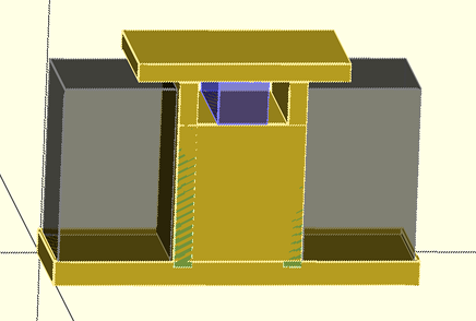
Speaker set model. Grey boxes are speakers (translucent), blue box is amplifier. (Note the top, plus 1/8″ lip around the speakers, prevent speakers from falling out unless carefully lifted.)
And this output:
Parsing design (AST generation)…
Compiling design (CSG Tree generation)…
ECHO: “Base”, 14.375, 0.75, 4.75
ECHO: “Long strip”, 14.625, 1, 0.125
ECHO: “Long strip”, 14.625, 1, 0.125
ECHO: “Short strip”, 0.125, 1, 4.75
ECHO: “Short strip”, 0.125, 1, 4.75
ECHO: “Pillar (less subtraction)”, 0.75, 7.625, 5
ECHO: “Pillar remove”, 0.25, 0.125
ECHO: “Pillar remove”, 5.875, 0.125
ECHO: “Pillar (less subtraction)”, 0.75, 7.625, 5
ECHO: “Pillar remove”, 0.25, 0.125
ECHO: “Pillar remove”, 5.875, 0.125
ECHO: “Shelf1”, 3.625, 0.25, 4.75
ECHO: “Shelf2”, 3.625, 0.25, 4.875
ECHO: “Power strip”, 3.625, 0.5, 0.125
ECHO: “Plate”, 5.125, 5.625, 0.125
ECHO: “Top”, 8.5, 0.75, 5
ECHO: “Clearance for speakers above lip”, 0.125
Compilation finished.
Compiling design (CSG Products generation)…
PolySets in cache: 15
Polygons in cache: 90
CGAL Polyhedrons in cache: 0
Vertices in cache: 0
Compiling design (CSG Products normalization)…
Normalized CSG tree has 21 elements
CSG generation finished.
Total rendering time: 0 hours, 0 minutes, 0 seconds
As you can see from the last line, this simple project renders nearly instantly.
From the cut list, I was able to go to my wood shop and cut out all the parts, ready to assemble:
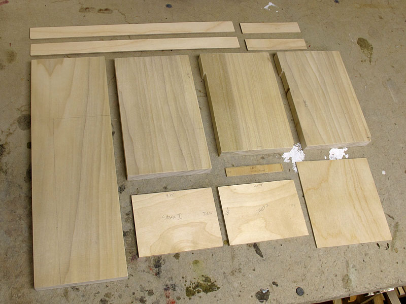
Speaker set parts, per the cut list
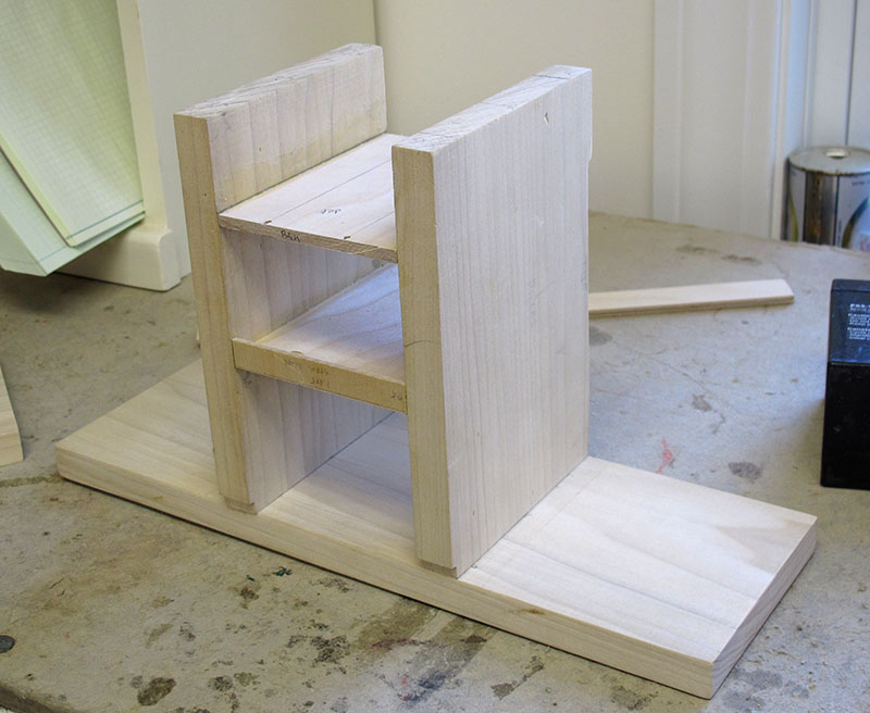
I quickly piled the pieces together to see if they really fit with the components…
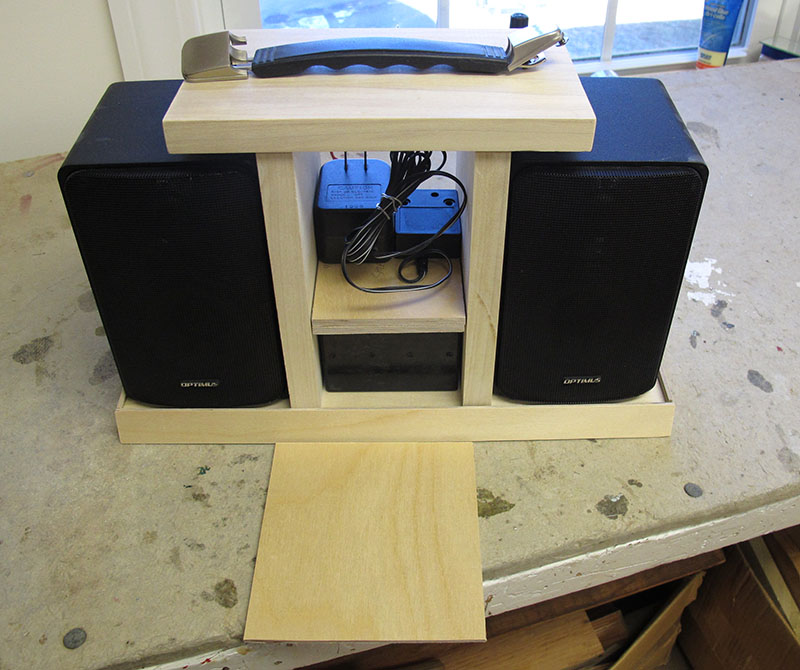
Front view. (Amplifier will go on top shelf.)
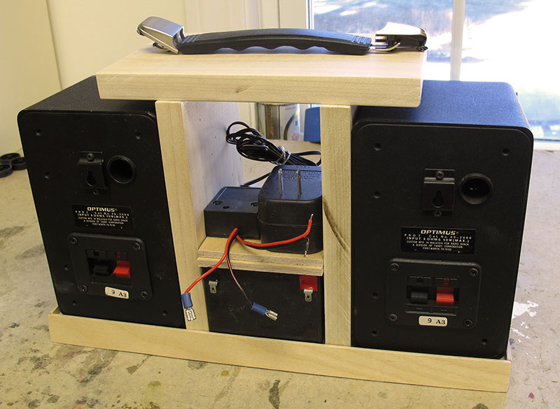
Back view.
…and they did! Perfect on the first try!
Here’s the case part way thru assembly:
Case partially assembled.
And the finished product, painted and wired up:
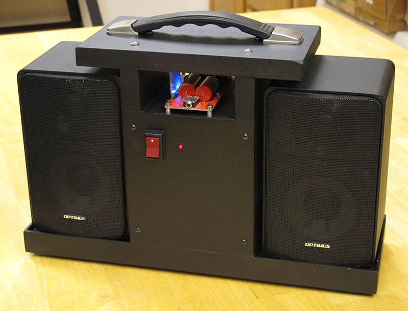
Front view.
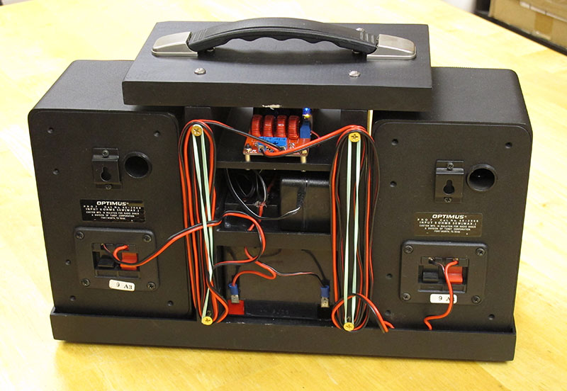
Back view.
It sounds good, too.
#1 by Bob on 2013 March 28 - 01:20
Quote
It looks very professional. Nice work!
#2 by Tuomas on 2013 May 7 - 08:55
Quote
Nice work. Say – how does the switchin between line-in and BT work on the Amp board?
#3 by Dave on 2013 May 7 - 15:33
Quote
When you plug in the 1/8″ plug into the jack, it automatically cuts out the BT audio and takes the input from the jack.
I think they simply routed the baseband audio signal from the BT receiver thru the jack; the switchover seems to be purely mechanical.
The line-in appears to be a little louder than the BT output (maybe 3 or 4 dB).
Cheers,
–Dave
#4 by Max on 2013 May 10 - 22:44
Quote
I’m really keen on that amp as well especially since it’s coming with BT and seem to be ready to use out of the box. But how do you change the volume?
#5 by Dave on 2013 May 11 - 14:33
Quote
You change the volume on the phone or tablet that’s sending the BT signal.