Archive for category Software

Telemetry test flights, battery & parachute problems

This is another catch-up post on my GPS rocket navigation project.

As mentioned in my last post, over the winter of 2010/2011 I got the code working to drive the telemetry radio. I also built a new version of the PCB, “Rev 4.2.1”, the same one I’m flying now and discussed in this post.

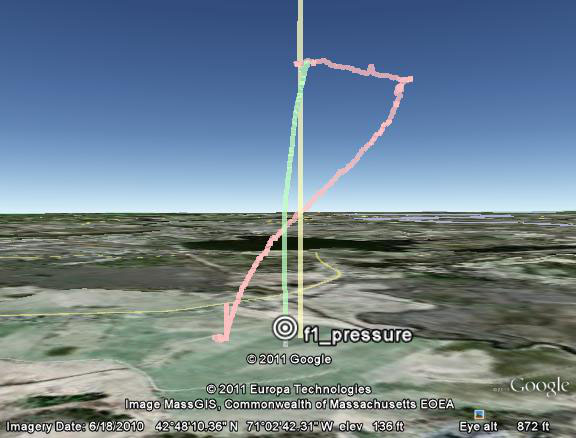
April 30 was my first chance to test the new telemetry system in flight I got in 3 flights that day – here is the first, my 4″ “SuperHorizon” rocket on a Skyripper H155PP:

The parachute deployed OK (eliciting some surprise), but there was no obvious steering of the parachute – it just spun around slowly counterclockwise (as seen from the ground).

Other than that, everything including the telemetry system worked fine until a few seconds before landing, when the telemetry stopped abruptly. On recovery, the electronics were completely powered down, and one of the two LiIon cellphone batteries had 4.1 volts on it (a full charge), but the other appeared short – so only 4.1 v was reaching the electronics, not enough to run it.

I didn’t know why the parachute didn’t steer, but I was happy enough that the parachute was deploying and the new hardware and telemetry stuff seemed to be working.

I tried to extract the log data from the PIC32 flash memory via the telemetry system, but there was nothing there. I wasn’t sure why (then) – it might have had something to do with the power system problem.

Since my goal for the day was to acquire navigation experience that I could analyze afterward, I went ahead and flew my 3″ “Thrud” on a Cesaroni H100. Here it is:

It got to 1577 feet AGL. This was just the second flight for the “Rev 4.2.1” hardware, and again it worked fine – this time with no power system problems. It seemed to steer somewhat back toward the launch pad, but the wind was also blowing that way, so it wasn’t so clear at the time if this was just good luck.

Again I had problems extracting the log data via the telemetry system. I was ultimately able to do it by connecting to the physical serial port on the PCB.

I still had time for one more flight. I decided to fly the SuperHorizon again after stealing the batteries from Thrud (since I didn’t trust the batteries that had failed on the first flight).

This time I shortened the forward parachute lines by about 1 inch, hoping to decrease the angle of attack and get a faster forward airspeed for the parachute. The wind was really low so I went with a bigger motor – a Skyripper J144:

As you see, shortening the forward lines resulted in a parachute that didn’t fully inflate. So I won’t do that again.

Again I lost all the logged navigation data from this flight. I did have some info from the telemetry, which showed a very confused navigation algorithm, with no consistent mapping of servo position to turn rate, and no consistent system lag values. Some of this might have been from the poorly-inflated parachute, but it wasn’t a good sign. I was concerned that the swinging of the whole electronics bay (including the GPS) under the parachute was confusing my navigation algorithm – the swings were so large that I imagined the GPS could think it’s heading in the direction of the swing, while the parachute itself was going in a completely different direction. At the time, that was my theory as to why the navigation wasn’t working.

Post-flight analysis

It turned out that cellphone LiIon batteries have an over-current protection circuit, which is supposed to reduce the chance of the battery catching fire in case of too much current draw. On the first flight, the servo loads triggered this circuit in the “short” battery. Once I ripped that circuit board out of the battery, that cell was fine. Lesson learned – I now take the over-current protection circuit board out of all my batteries before flight.

The logging data turned out to have been lost because of a minor bug in the way I was handling buffer overruns in the telemetry software – this was easy to fix once I’d discovered it.
Rocket telemetry system

Last winter (2010/2011) I finally got around to writing code that drives the Microchip MRF24J40MB transceiver module on the PCB for my GPS-guided rocket recovery project.

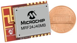
The transceiver module is a very nice little part – it’s an IEEE 802.15.4 (ZigBee) radio that uses the 2.4 GHz ISM band – the same band that WiFi and microwave ovens use. The “-MB” is Microchip’s long-range module – it has the radio, antenna, power amplifier (PA), and low noise amplifier (LNA) all on a surface-mountable board a bit bigger than a postage stamp. It comes pre-approved by the FCC for unlicensed use. And the price is reasonable.

Here’s a pic showing the size:

It outputs 100 mW (20 dBm) and has a receive sensitivity of -102 dBm, so the range is quite good; well over 2500 meters outdoors (line of sight).

Microchip also offers a “-MA” module that’s both smaller and cheaper, but it only outputs 1 mW and doesn’t have the LNA, so it has less range.

It talks to the MCU with a simple 4-wire serial SPI interface; internally it has a lot of registers – you send it SPI commands to read and write the registers.

I’d already included an interface to the module on my PCB layout (posted elsewhere on this site – see here), so now I had to write some code that would talk to the module.

My goal was to get real-time telemetry from the rocket in flight, as well as to be able to send the rocket commands from the ground. I was already logging flight data to the flash memory in the PIC32, but if the rocket isn’t found I can’t get that data out of the PIC. So at a minimum, I wanted to get GPS fixes in flight, so if the rocket is lost I know where to go looking for it.

As well, the ability to send commands to the rocket is useful. With the telemetry system I can arm/disarm the ejection charges from a safe distance, as well as manually force ejection, switch modes, and power down the PCB (to save battery power after a scrub).

Software

IEEE 802.15.4 is the basis of ZigBee, a rather complicated protocol for smart gadgets and appliances to talk to each other wirelessly. Microchip offers source code for the entire ZigBee stack, but I didn’t need anything like that kind of complexity for this application.

Microchip also offers source code for something they call “MiWi P2P”, which is a vastly simplified protocol that implements a small subset of the ZigBee functions (it’s not compatible with ZigBee).

I had a look at the datasheet for the MRF24J40 transceiver chip – it’s 156 intimidating pages long. So I decided to use Microchip’s MiWi P2P source code, thinking that would be an easier solution than figuring out the datasheet and writing my own code.

That was a big mistake, at least for me. The MiWi P2P code has lots of functionality that I didn’t need – it will route messages around a network of peer devices, do store-and-forward for sleeping radios, etc. All I needed was simple point-to-point transmit and receive. So I started to modify the code to simplify things – all that functionality was making the interface to the rest of the system needlessly complicated. In the process of doing that, I found lots and lots of problems and bugs in the MiWi code. I ended up spending several weeks porting and debugging it; by the end I’d rewritten 98% of it (and thrown away a good 85% as useless overhead for my application). I used version 3.1.3, which is no longer the latest, but I don’t think the newer versions are much better.

The MiWi P2P code does work if you treat it as a “black box” and don’t attempt to do anything other than the few example things documented by Microchip. The bugs either aren’t exercised or are worked around for those cases. But if you want to customize or optimize anything at all you quickly run into trouble. It’s a bloated, buggy, poorly written and poorly documented piece of code. (It is well-architected. And it is free.)

In the process of rewriting the MiWi code, I learned how the MRF24J40 hardware works, and how to code to it myself. It turns out that “intimidating” 156 page datasheet isn’t nearly as bad as it first seems – from a software point of view, you only need to read sections 3.2 (Initialization), 3.11 (Reception), and 3.12 (Transmission) – that tells you everything you need to know in less than 10 pages! (It helps to skim over the IEEE 802.15.4 document first to know what to expect – but you don’t have to implement all of it to get simple data transfer working.)

If you’re going to do this yourself my advice is to ignore Microchip’s source code and write directly to the MRF24J40 hardware per the datasheet, unless you really need the whole ZigBee stack. Follow the datasheet’s initialization instructions exactly. Do not even look at Microchip’s application notes – they’ll only add confusion.

If you do that, you can have it running with 2 or 3 days of work (instead of the 2 or 3 weeks I spent). The hardware is excellent and it works like the datasheet says.

[Update January 2012: I’ve posted the source code; see: http://nerdfever.com/?p=1797]

Once I had basic radio I/O working, I implemented a set of commands the rocket would respond to – they’re all simple ASCII strings (think a command-line interface). Here is the list as of this writing:

STATE NAMES (forces rocket software into commanded state)

NONe
SAFe
ARMed
TLAunch (timed launch – used for ground testing)
ASCent
DEScent
GROund
TESt

NOUN ALONE

DUMp (dumps log as hex)

RESET-LOG *
RESET-NAV *
RESET-ALL *
POWER-DOWN *

* must type whole command for these

PARAMETER COMMANDS (noun verb)

(no parameter = report current status)

CHAnnel n (set radio channel)
BUZzer on/off
BEEp on/off
LOWbuz on/off
GPS_enable on/off (GPS power)
DROgue on/off (drogue output)
MAIn on/off (main parachute deployment output)
ST2 on/off (“stage 2” output)
ST3 on/off (“stage 3″output)
RED on/off (LED)
YELLow on/off (LED)
GREen on/off (LED)
VSWbatt_pwr on/off (switched battery power circuit)
VSErvo_pwr on/off (servo power)
STEer / S 0 to 255 (both servos same)
S1 0 to 255 (servo #1)
S2 0 to 255 (servo #2)
UPDates on/off (transmit updates every 40 mS)
LTHreshold  meters (launch detect threshold)

PARAMETERS

<integer> value
ON 1
OFF  0
TOGgle  !<oldValue>

I only have to send the capitalized characters (usually the first 3); the rest are ‘syntactic sugar’ to make it easier for me to remember them.

In addition to responding to the commands, the rocket will also send status information each time the software changes state (for example, when launch is detected and the rocket goes from ARMED to ASCENT) and on each GPS fix and each cycle of the navigation algorithm (for diagnostics/debugging).

Ground station

Now that I had telemetry software in the rocket, I needed a ground station to talk with the rocket.

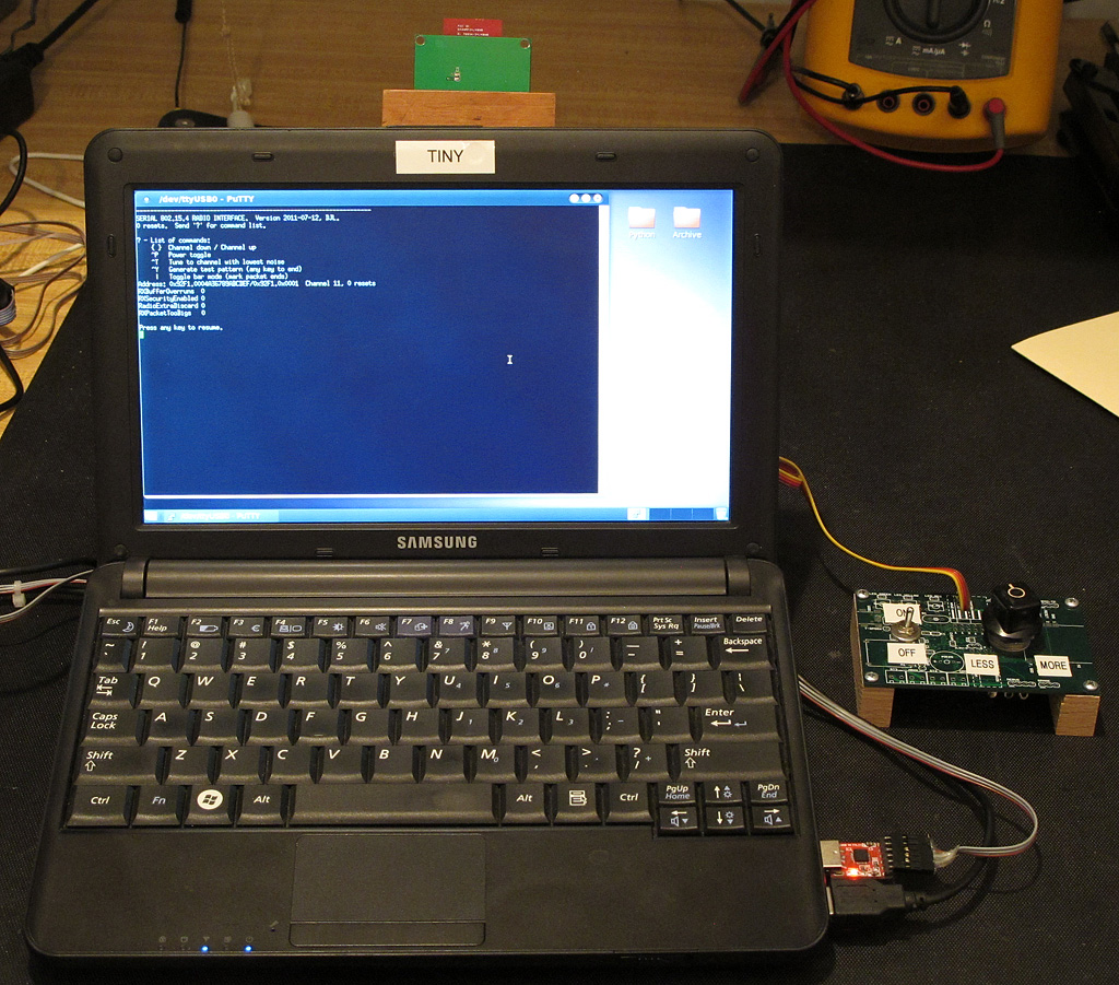
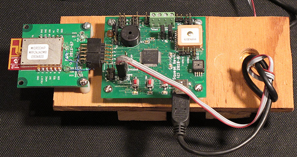
The ground station consists of a 802.15.4 radio that talks to the rocket, plugged into a netbook computer that acts as a terminal. Here’s a pic of the ground station radio:

Look familiar? It’s pretty much the same PCB that goes in the rocket – this was an earlier spin of the PCB that didn’t work out too well – I’d used a ADP3335 LDO as a voltage regulator, but forgot to put in any heatsink for it. The LDO got too hot for comfort when running of the 7.4v flight battery, but it wasn’t bad when running off the 5v USB from the netbook, so I used the board as the ground station radio. (As you can see, I was experimenting with making the radio module a separate board at the time.)

There are two USB connectors that go to the netbook – one powers the board, the other has a USB-to-serial converter on it, because I still haven’t gotten around to writing a driver for the USB port on the microcontroller side. On the netbook side I’m just running a terminal emulator (PuTTY if you must know) for now – in the future I’m planning to write something that will process the data in real-time to produce plots, etc.

Here’s the netbook, with the radio attached by velcro to the back:

It’s a Samsung N130 running Ubuntu. There’s no particular reason to run Ubuntu instead of Windows (my usual OS) for now, except that Ubuntu seems to be a better-supported Python development environment, and eventually I plan to write some Python code to talk to the rocket in real-time. And it was a good excuse to play around with Ubuntu a little.

One major change I made to the netbook was to replace the standard LCD screen with a Pixel Qi display. Normal (backlit) LCDs are almost impossible to read in direct sunlight – and rocket launches are very often outdoors. I’ve had terrible problems trying to read laptop screens at launches. So I bought the ridiculously overpriced display from Maker SHED ($275 plus shipping for a display to go in a $300 netbook!).

Although I still grumble about the price, the Pixel Qi display is great. It’s a normal color LCD except that, in addition to the backlit mode where it acts like any other LCD display, it has a reflective layer that makes it readable in full sunlight – the more light the better. Some people call this a separate “mode” from when it’s backlit, but there really isn’t a mode – the display is reflective all the time, but you can’t tell unless there is a lot of light.  If there is so much ambient light that it washes out the backlighting (outdoors), you can just turn off the backlight altogether and save the battery power it consumes.  The reflective mode is black-and-white, but that’s fine with me – it’s readable and I love it.

While I had the netbook apart, I swapped out the HDD for an 80 GB SSD – so it runs a little faster now, with no moving parts except the CPU fan.

Universal controller

Lastly, after a few test flights (which I’ll describe in an upcoming post), I decided that I wanted a way to manually steer the parachute, mainly so I could try to analyse what the navigation system was doing with known steering inputs (which didn’t work for reasons I’ll explain later too).

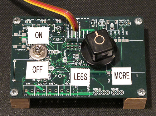
So I built what I call the “universal controller” to steer the parachute:

It’s nothing but a potentiometer and switch.  But, hey, on/off and less/more – what else could you possibly need?  🙂

The pot is connected to an analog input of the microcontroller on the ground station PCB. When the switch is set to ON (switch is attached to a digital input), the position of the pot is read and transmitted as a steering command to the rocket; the steering servo just tracks the position of the knob. When the switch is OFF, the rocket steers itself with the on-board navigation algorithm.

The telemetry system has worked very well, at ranges of well over a mile.

Steering with a tiny baseline; or trying

Continuing with my update on my GPS rocket navigation project, in this post I’ll quickly run thru my progress (or lack thereof) in latter half of 2010.

17 July 2010 – Flight #28 – First navigation attempt

Last year I posted a video of flight #28 of 17 July 2010, which was my very first flight with the GPS navigation software running and the steerable parachute.

As I mentioned in my recent post, that flight used a steering baseline of just 2.5 inches, yet the system appeared (from the ground) to be able to steer the parachute OK with that tiny baseline. Here’s the video (again):

As can be seen in the video, the rocket appeared to be steering purposefully, although not in the right direction. So I came away with the idea that (somewhat to my surprise) a tiny 2.5″ baseline was a workable thing.

Below, the red arrow shows the 2.5″ baseline – the distance from the left steering line (kevlar braid) to the right steering line.

Here’s the plot of the flight path (click for the Google Earth KML file):

The navigation didn’t really work at all, but this was my very first attempt and I didn’t expect much; I knew there were a lot of variables in the navigation software that would need tweaking from flight experience. The winds aloft were much higher than expected and the rocket landed way off the field – 40 feet up in a pine tree. It took me 4 days to find it and get it down, but I’ll spare you that sob story.

One thing that came out of the flight was a determination to get the telemetry radio working – if I’d had that on this flight, I’d have had the GPS coordinates of the landing site, and it wouldn’t have taken days of searching to find the rocket.

18 September 2010 – Flights #29 and 30 – Test of piston ejection

The July 17 flight also had a problem with the ejection charge burning the steering control line to the parachute.

To avoid that happening again, I redesigned the rocket to use piston-type ejection, where the electronics bay is the piston. That way, instead of having the ejection charges on the parachute side of the electronics bay (where they can burn the control lines), the charges are on the opposite end of the electronics bay. The charge fires into the space between the altimeter bay and a fixed bulkhead in the body tube. The whole electronics bay slides out, pushing the parachute ahead of it.

Earlier in the year (April), I’d run some ground tests in my backyard to find out how big a BP charge was needed for piston ejection. I’d been using 3 to 4 grams of BP in conventional (non-piston) ejection in my 3″ and 4″ rockets. Here’s a video of the tests with the piston, in my 3″ rocket “Thrud”:

I started with 2.5 grams – I didn’t mean to build a cannon, but it seems I did. I ended up using just 0.5 grams of BP in the 3″ rocket (“Thrud”), and 750 mg in the 4″ rocket (“SuperHorizion”).

Two flights on 18 September tested the new system (without any attempt at navigation); it worked perfectly (and has continued to work great since). I’m sticking with piston ejection!

2 October 2010 – Flight #31 – Bad chute deployment

By October, I’d made a few software tweaks, had the piston ejection working smoothly, and was ready to try again with navigation. Here’s what happened:

The parachute lines were horribly tangled up, which prevented the parachute from inflating.

6 November 2010 – Flight #32 – Another crash

By the November launch I fixed the damage and was ready to try again:

Oof. Again, the parachute lines tangled in flight, resulting in a crash. This time there was no damage (just lucky).

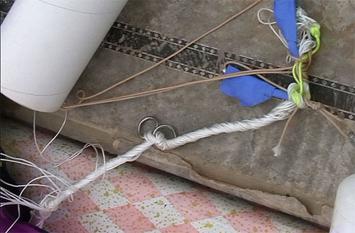
Here are a couple of stills from video, showing what the parachute lines looked like at recovery – all twisted and tangled:

6 November 2010 – Flight #33 – Some navigation! ?

Undeterred by the tangling/twisting problem, I packed the parachute and lines even more carefully and tried again.

Despite the taunts from my long-suffering fellow club members (they’ve seen a lot of my failures), the applause at landing was encouraging, even though I wasn’t sure at the time if the navigation was real or just good luck with the wind.

It was a low altitude flight – just 650 feet AGL on a Cesaroni H133 motor (a very small H), so the navigation system didn’t have a lot of descent time to learn to fly the parachute.

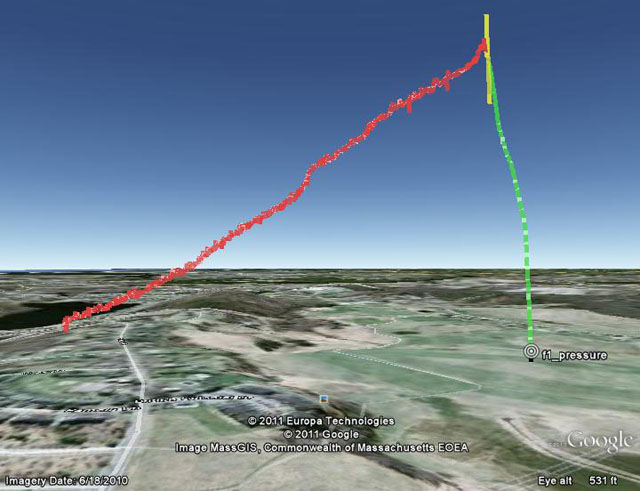
Here is the flight path as plotted in Googe Earth (again, click to download the KML file):

From the ground the parachute appeared to have deployed OK, but on recovery I found, again, tangled lines, but not as bad as in the previous flight. Have a look:

After the flight I had a careful look at the logged navigation data (including the internal state of the navigation algorithm) and decided that the rocket probably had navigated successfully for part of the flight – at least for a few seconds of the short descent. So this was a real milestone.

More importantly, I’d learned a lot. The tangling issue was clearly an ongoing problem, even with the most careful packing.

Looking at the video, I became concerned that another problem might be the swinging of the whole electronics bay (including the GPS) under the long parachute lines. Since the rocket estimates its flight direction based on sucessive GPS fixes, a significant swing could easily confuse the rocket into thinking it’s heading in the direction of the swing, instead of the direction of the parachute’s flight.

Club member Boris Katan – a much more experienced rocketeer – suggested that my parachute lines were much too long. I’d made them long to reduce the impact of the short baseline on the angle that the steering lines reached the parachute, but Boris convinced me to vastly shorten the lines – both to reduce the swing, and also to reduce the chance of tangling.

21 November 2010 – Flight #34 – Last launch of the 2010 season

The next launch on 21 November was the last of the year (here in Boston we get snow soon after that).

With much shorter lines to the parachute, I launched the 3″ “Thrud” rocket again, on an Aerotech H180:

That was bad.

In my earlier flights, I’d been using one of Robert DeHate’s PICO-AD4 altimeters as a backup to my own electronics for deployment. But I’d made some software changes to save battery power on the pad by powering down the servo until launch was detected. Inadvertently, that had also disabled power to the AD4 altimeter.

So as a quick “fix” to provide backup deployment in case the first flashbulb didn’t go, I’d wired two flashbulbs, with 0.5g of BP each, in parallel onto my own apogee ejection output. This was my half-baked ejection redundancy. It seems that 1g of BP going off at once was too much for the kevlar cord retaining the electronics bay/piston.

A lesson I learned late is to avoid using epoxy on Kevlar cords – I’d plugged the hole where the cord went thru a bulkhead with epoxy, but epoxy is stiff and doesn’t let the other fibers in the cord take up strain. So the Kevlar becomes brittle and weak – it ripped right at the end of the epoxy. (Hot glue is a much better solution; it’s flexible so it still allows the different fibers to take up the strain.)

The whole e-bay was ejected from the main body tube, together with the parachute and nose cone. The bottom plate of the e-bay (with the ejection charge holders and power switch) and the tube around it were ripped off (never found that). The wires running to the flashbulbs and power switch were ripped off at the PCB.

As you saw in the video, without the weight of the back end of the rocket, the parachute drifted a long way, bounced off a power line, and landed in the dreaded CMASS swamp.

The only good thing was that my PCB kept running, as it’s designed to turn off only when the power switch is closed (not open).

So that was it for the 2010 season.

I’d had one good flight of the system. That had worked only a little bit. But I got valuable data from the flight, which I was optimistic would enable me to tweak things so they work properly. The tangling problem was clearly serious, but I hoped that the shorter parachute lines and careful attention to packing of the parachute would address that in the new year.

Truck tests of GPS-driven autonomous navigation

This post continues my update of progress toward a steerable parachute system that automatically returns rockets to the launch pad.

In early July 2010, coding of the navigation software was done – it worked well in the simulation, but as a reality check I built another truck to at least test it on the ground.

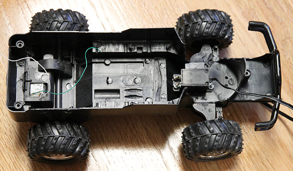
I stripped a $15 toy truck down to the chassis and installed an old hobby servo to steer it:

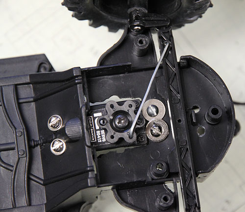
Here’s the sophisticated steering linkage – a bent paper clip:

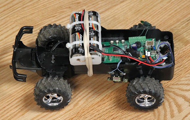
Then I stuck the CPU board in there with some batteries to run the truck motor:

There was no R/C radio – the system is autonomous and steers itself.

This one wasn’t as robust as the truck I’d tested back in 2006 or so (see my slides) – that was a $80 toy truck, and big enough to run on grass and drag around a whole laptop and lead-acid battery- but I didn’t need the laptop anymore since the navigation was running on the flight hardware. It was good enough for a quick-and-dirty test in a nearby parking lot.

It was a very useful test – I found lots of bugs, as documented in my notes. But, after a mere 6 or 7 tries over the July 4 weekend, it was successfully navigating its way around the parking lot. The road to flight glory seemed open.

Update on latest “Rev 4.2.1” PCB, tips and status

It’s been quite a while since I posted an update on my GPS-steered parachute for recovery of rockets. This is is the first in a series of posts where I’ll try to bring things up to date.

(For those who want way-too-much-dry-detail, my Flight Test Notes updated thru August 2011 are here; by the time you read this, there might be a newer version linked from the main project page.)

The bottom line is that, as of this writing (August 2011), it’s not working yet, but I think I’m very close. I seem to have have been sidetracked for a whole year by using a very small baseline (horizontal distance between the left and right parachute control lines) to steer the parachute. My flight #28 in July 2010 seemed to work OK with a tiny baseline (just 2.5 inches), so for the past year all my flights have used small baselines – and none of them have steered very well (altho some worked a little bit). Only in July 2011 did I realize the small baseline was causing most of my problems – the steering lines simply get twisted together, preventing steering.

I’ll get to how I figured that out, and what I plan to do about it, in future posts.

Current hardware – Rev 4.2.1 PCB

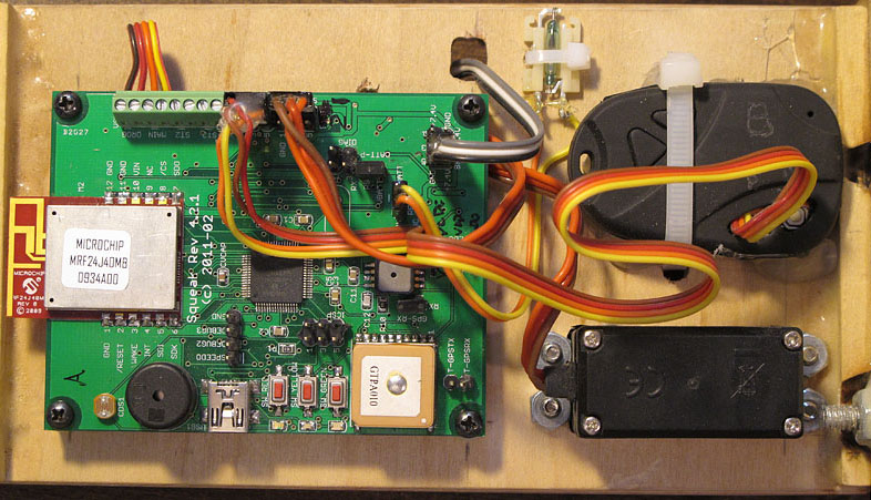
Here’s a picture of the hardware I’m flying now – I call it “Rev 4.2.1”:

It’s a slightly-updated version of the Rev 4.1 board I posted earlier:

  • Microchip PIC32 MCU (PIC32MX440, with the USB interface),
  • GlobalTop PA6B GPS (updates at up to 10 Hz),
  • Microchip MRF24J40MB IEEE 802.15.4 radio transceiver for telemetry,
  • Freescale MP3H6115A pressure sensor for the altimeter,
  • Some buttons, LEDs, and a piezo beeper,
  • A USB port that right now is only used to power the board on the test bench,
  • Some MOSFET switches to drive four pyro outputs (on the back side; not visible)
  • Logic power is 3.3v from a Microchip TC105 switching DC-DC converter (also on the back side) – this is much more efficient than my old LDO design – the board can now sit on the pad for hours without me worrying about the battery dying.

I layout the board in Eagle PCB and have them made in China by BatchPCB.com, then populate the boards myself by hand with a soldering iron, heat gun, stereo microscope, and patience.

It runs off 6 to 9 volts; normally I use two LiIon cellphone batteries in series (see next pic) or 6 NiMH cells in series.

At this moment I have a very slightly updated version (Rev 4.2.2) out at BatchPCB being made, but I’m aiming for a new version this winter which will, I hope, run off a single LiIon cell (3.6 v) and have a charging circuit on board, so it’ll charge off the USB port.

Also visible in the picture is the back side of the steering servo, and the 808 keychain camera I’ve written about before. This looks upward at the parachute in flight, and has proved extremely useful in diagnosing what is going on with the parachute and steering (see videos linked in the Flight Test Notes).

Note the little glass-bulb thing at the top between the PCB and the camera. This is a magnetic reed switch, and it’s how I turn on the board inside the rocket without making a hole in the rocket for a switch. Unlike a Hall effect sensor, the reed switch doesn’t draw any power at all. I hold a magnet on the outside of the rocket, opposite the reed switch. The switch closes while the magnet is there, which powers up the CPU. As soon as the CPU boots, it pulls up an output line to keep the power on, even after the magnet is removed.

I can turn the power off with the reed switch too (the CPU monitors the switch as an input), but these days I usually power down with a telemetry command – when the CPU gets the command, it drops the same output line and turns itself off.

Electronics sled

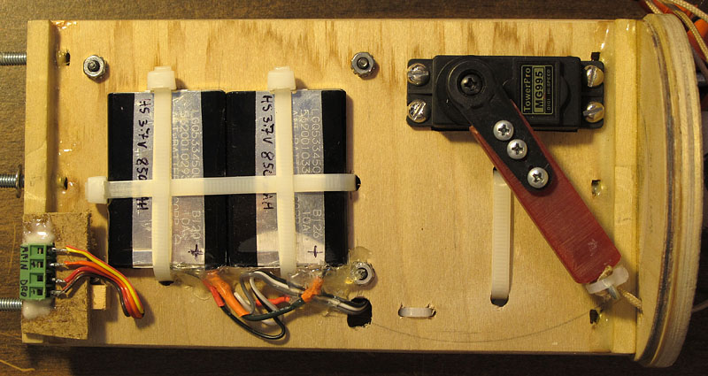
Below is a picture of the back side of the e-sled, with the batteries and servo top visible.

A few lessons I learned the hard way:

  • Pot wires with hot glue, not epoxy. Potting is important to keep wires from flexing and eventually breaking, but epoxy is brittle – the wire will flex exactly where the epoxy ends. Hot glue dries rubbery, so it allows some gentle flexing but spreads the load out along the wire. It’s easier to remove if you have to, too.
  •  

  • Modify cellphone LiIon cells before using them in another application. Cellphone LiIon cells have a protection circuit – usually a tiny PCB mounted at the connector – which limits charge and discharge current for the battery. Lithium batteries can catch fire (or theoretically even explode) if improperly charged or damaged – these circuits are supposed to prevent some of that, but the circuit can turn off the battery just at the critical moment when you need maximum current from it (it happened). So rip those boards out and connect directly to the cell. (And take proper precautions in general.)
  •  

  • Note the screw terminal connector at the end of the payload bay. This position lets me connect up the ejection charges without having to remove the whole e-sled and use long wires – my next spin of the PCB will mount the screw terminals on the end of the board directly, so I don’ t have to remotely position them this way.

Get PuTTY to work at 460800 bps in Linux

If you run PuTTY on a serial port under Ubuntu 10.10, it won’t set any bit rate higher than 230,400 bps. Even if you tell it to, any higher speed just gets you 230,400 bps.

Here is a workaround – create a file ‘fastterm.sh’ with the following contents:

putty -load myconfig&

sleep 1

stty -F /dev/ttyUSB0 speed 460800

stty -F /dev/ttyUSB0 speed 460800

(Yes, twice.) Replace “myconfig” with the name of your PuTTY config (mainly to setup the device name), and replace ‘/dev/ttyUSB0’ with your device name. (ttyUSB0 is the 0th USB serial port.)

To run it, use ‘sh fastterm.sh’.

Automatically email status for NVIDIA and Windows RAID arrays

A couple of years ago I posted my “CheckRAID.bat” routine for detecting problems with a Windows software RAID.

I’ve done a new version. This one works not only with Windows software RAID arrays, but also with NVIDIA motherboard supported RAIDs. And this one emails you a report automatically.

RAIDs are great for backup; a RAID 1 or RAID 5 array will preserve your data intact even if one of the drives in the array fails. But if two or more drives fail, you lose your data. So it’s important to know when you have a failed/failing drive, so you can replace it before a second drive fails.

Unfortunately neither Microsoft nor NVIDIA provide any way to know when this is happening, other than manually looking in the system log files, or (in NVIDIA’s case) manually running their “NVIDIA Control Panel” app to check the health of the array.

So I cooked up a little Python routine that checks the system logs automatically, and emails a report.

I call this version CheckRAID2; click the name to download it as a ZIP file (about 15 MBytes; almost all of that is the Python installer). It’s freeware (public domain).

Unzip it into a folder (anywhere you please, but you’ll need to keep the folder around, so put it where you don’t mind it) and follow the instructions in the README.txt file to set it up. You’ll need to install Python if you don’t already have it on your system – the download includes the Python installer (Python is free).

As far as I know, this is the only automated RAID status check that supports NVIDIA’s motherboard-driven RAID arrays.

If you find this useful, I’d appreciate a comment.

“Rev4” PCB and software

[Update October 2011: This post is no longer the latest version version of the board; see here.]

Almost a year ago I posted the schematics and software for the “Rev3” version of my rocket flight computer/altimeter.

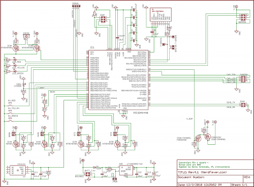
I’ve now got the code ported over and working well on the “Rev4” hardware. This is far more integrated – the parachute deployment circuits, piezo speaker, and GPS are all on the PCB now, and it’s based on the much more powerful PIC32 MCU. So (per a couple of requests), I’m posting the software and schematics for that today.

Rev4.1 Schematic (click for full size)
At this point I do have navigation software that (in theory anyway) steers the rocket’s parachute to return back to the launch pad. It seemed to work the one time I’ve had a chance to try it (November 6 – you can read the details in my flight test notes here). It still needs a good deal of tweaking before it’ll be working as well as I want it to – that’s a project for next year’s flying season. One day I’ll get around to posting a full update on the project here.

The code I’m posting today, like the earlier “Rev3” code, does not include the navigation code. But it does include everything else – logging altimeter, parachute deployment, GPS, servo control, etc. Because of the “abuse potential” of the nav code (think of navigating things to places where they ought not to be), I don’t intend to make the nav source code public. Once it’s working well, I might be interested in working with reputable vendors to sell hardware that includes this function, but if I do, it’ll have some protections in place against abuse. The main protection I’m considering is to limit the target location the system will aim for – it has to be a place the unit has physically been since it was powered up (you won’t be able to program in some other location). That way, if you’re not allowed to go somewhere with a handful of blinking rocket electronics, you can’t land the rocket there either. I’d like feedback on this idea. (Yes, anything can be hacked if you put enough effort into it, but my goal is to make it harder to hack the system than for “bad guys” to build their own – there are, after all, books on the subject…)

Anyway, here are the links to the hardware design (schematics only) and software. The deal on rights is exactly the same as with the “Rev3” postings:

Hardware rights: I hereby grant everyone and everything in the universe permission to use and modify this hardware design for any purpose whatsoever. In exchange, you agree not to sue me about it. I make no promises. By using the design you agree that if you’re unhappy the most I owe you is what you paid me (zip). That seems fair.

Here is the schematic for the hardware, in both PDF and as the original CadSoft EAGLE file (see also the ReadMe.txt in there): Rev4.1Schematic.zip

And for the software:

Software rights: I hereby grant everyone and everything in the universe permission to use and modify this software for any NON-COMMERCIAL purpose whatsoever, PROVIDED that you (a) agree not to sue me about it, (b) credit Nerdfever.com as the original source of the software in any publications, and (c) agree that I make no promises and that if you’re unhappy the most I owe you is what you paid me (zip, zero, nada, nothing). Oh, and you agree to USE THIS AT YOUR OWN RISK, that you’re a responsible adult and know that rockets can be dangerous and hurt people if you’re not careful (regardless of whether or not software is involved) so you’ll be careful and will not blame anyone else if you screw up (especially me).

I’ll be very pleased if you leave a comment or drop me an email if you find it useful, but you don’t have to.

For COMMERCIAL use, ask my permission first. If you’re going to make lots of money off my work, I’d like a (oh-so small and reasonable) cut. But I’ve no intention of giving anybody heartache over small amounts – just ask, I think you’ll find me surprisingly easy to deal with.

Here is the the Rev4 code for PIC32, including the Microchip MPLAB IDE project files, just as it appears in the project folder: Rev4.1Code.zip

Although it’s improved in lots of minor ways, the structure of the code is very similar to the Rev3 code, so please use the 6-part posting from last year as a guide to the software. The main UI change from then is that arming/disarming is now done via a reed switch. This lets me arm and disarm the system on the launch pad using a magnet, so I don’t have to make holes in the rocket body for a switch (and worry about lining up the switch with the hole). (Search for “MAGNET” in the code).

Feedback and suggestions for improvement are very welcome. I’m very happy to help out anyone who wants to work with this stuff – just drop me an email or post a comment here.

Video editing for scientific analysis

Or, Sony Vegas 101

Over the last few weeks a lot of my spare time has been going into learning how to edit videos – mostly of rocket launches and tests. Video is a great medium for capturing and carefully reviewing fast-moving objects – a standard (NTSC) camcorder captures 60 fields (half-frames, sort of) each second, which gives you a lot of time resolution to see what is going on.

For the last dozen years or so, ever since video editing became reasonably practical on a PC, I’ve periodically attempted to learn how to edit video, but it always seemed impossibly complex. This was despite the fact that I have a pretty good technical background in video – I sat on the the committee that developed the H.264 standard. (Hi Gary, Hi Thomas. I don’t miss your meetings at all.)

But I’ve finally managed it, and it turned out to be much less bad than it seemed (as usual). I’ll try to pass along the key tricks to getting it working.

Caveat: My focus has been on editing digital video from a consumer-type HD camcorder (a Canon HF100), for ultimate viewing on a computer (a Windows box). So I’m assuming you have already copied the .MTS files of your video clips from the SD card and have them to start with.

I’ll start with the Executive Summary (applicable to rocketry-type videos), then explain:

  • Camcorder setup (Canon HF100 or similar):
    • Use a gun sight as a viewfinder
    • Shortest possible shutter speed (1/2000 second is good)
    • Manually focus at infinity (turn off autofocus)
    • Turn on image stabilization
    • Set highest possible bit rate
    • Record at 60i
    • Get far away (> 100′)
  • Video editing – use Sony Vegas
    • Project settings
      • 1920×1080
      • 59.94 frames/second
      • Progressive scan
      • Deinterlace by interpolation
      • 32-bit floating point (video levels)
      • UNCHECK “Adjust source media”
    • Preview rendering quality: Set to Good (auto) or Best
      • Anything less than Good won’t de-interlace (on preview)
    • Add Sony Color Corrector
      • Gain = ((17+255)/255) = 1.06666667
      • Offset = -17
    • Options>GridSpacing>Frames
    • Options>Quantize to Frames
    • Output: Render As…
      • Audio: Default stereo at 44.1 kHz
      • MainConcepts AVCHD (H.264):
        • 1920×1080 (do not resample)
        • Progressive scan
        • Best
        • Main profile
        • 2-pass VBR (for quality)
        • Use CPU only (only if you get errors with the GPU)
  • 4 Mbps minimum; 10 to 14 Mbps is better

ABOUT VIDEO

Just like Thomas Edison’s motion picture film, video is a series of still pictures that are captured and shown in quick succession, to create the illusion of smooth motion. When you’re going to carefully analyze an event after the fact, it can be really helpful to look at those still pictures one at a time, or in slow-motion. You can easily measure the duration and timing of events by counting frames (pictures), because the frames are taken at fixed intervals of time.

In NTSC countries (USA, Canada, Japan), the standard video format is 30 frames (pictures)/second, in the rest of the world it’s 25 frames/second (PAL and SECAM standards). Since I’m in the USA I’m going to use the 30 frames/second number (adjust accordingly if that doesn’t fit where you live).

So, for example, if frame 30 shows an event starting, and frame 36 shows it ending, you know the event was 6 frame intervals long. That’s 6/30ths of a second (0.2 seconds).

Only…it’s not really 30 frames/second, it’s actually (30 * 1000/1001) frames/second, which is a tiny bit more than 29.97 frames/second. The reason for that is related to the transition from black-and-white to color broadcasting in the 1950s, the details of which are irrelevant today. Just accept it – when people say “30 Hz” in video, they mean 30 * 1000/1001  Hz. (They also mean that if they say “29.97 Hz”, which is a lot closer to the exact value, but not quite there.)

Sometimes you’ll hear about “progressive” video, often abbreviated to “p” as in “720p” and “1080p”. Progressive video is what you’d expect video to be – a simple series of still pictures captured and shown one after another, like frames of a movie film.

Other times you’ll hear about “interlaced” video (as in “1080i”). That…I’ll get to.

VIDEO CAPTURE WITH THE CAMCORDER

I’ve been using a Canon HF100 consumer-level HD camcorder. It’s pretty good. My only complaints are that it has a mild rolling shutter problem (not nearly as bad as my DSLR’s video mode), and a clunky UI for manual control. The newer models are probably better.

Viewfinder – use a gun sight

The biggest problem I’ve had with it is tracking fast-moving rockets with the non-existent viewfinder. I don’t count the LCD screen as a viewfinder – because it’s 4 inches from your nose, your eyes can’t focus on the screen and the distant rocket at the same time. And if you look at the LCD screen, then the moment the rocket (or whatever) goes off the screen, you have no idea what direction to go to find it. This is a serious problem when you’re zoomed in a long way, as your field of view is small.

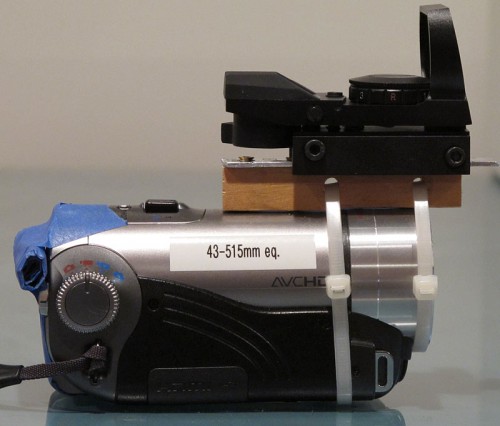
After trying several alternatives (“sports finders”, cardboard tubes, optics), the best solution was to attach a gun sight to the camcorder. It has no magnification, just projects a target into your field of view. It has little set-screws for adjusting it, so you tweak these until the target points at the exact middle of the picture when the camera is zoomed in all the way. That way, as long as you keep the target on what you’re trying to shoot, it’ll be in the picture. The one I used cost about $45; I attached it with cable ties, a block of wood, some Blu-tack (under the wood), and a strip of scrap metal.

Canon HF100 camcorder with gun sight viewfinder. The masking tape is to prevent my face from hitting the “record” button.

Setting up the camcorder

The camcorder has dozens of things you can set. These are the ones that matter for videos of fast-moving things like rockets:

Shutter speed – set to 1/2000 second (or whatever is the fastest it’ll go)

The less time the shutter is open, the less motion blur you’ll get in each picture. As long as you’re shooting in daylight, there will still be enough light – the camera will open up the aperture and/or crank up the gain to compensate. Don’t set the shutter to “auto”; it’ll be much too slow to freeze fast motion and you’ll get blur. (“Auto” is fine for videos of your kids.)

Use manual focus
Read the rest of this entry »

Is MS Word 2003 loading slower and slower?

It was for me. Turned out that that my Normal.dot file, usually 38 kBytes, had grown to 1.4 MBytes. That’s what was taking so long – loading it each time.

Simply deleting the file was a good temporary fix back in May (Word automatically re-creates it if it’s missing). On Win7 for me it was in:

C:\Users\Dave\AppData\Roaming\Microsoft\Templates

Lately, it’s been happening again – this time Normal.dot had grown to 1.8 MBytes (since May!).

Investigation revealed that the file grew by about 2 kBytes each time I loaded a file. I had a look at the binary of Normal.dot to see what was taking up so much space, and saw lots of Unicode text reading things like “Sign in to Office Live Workspace beta”.

So I un-installed “Microsoft Office Live Add-in”. Now Normal.dot doesn’t grow anymore.

This post is tagged “Sad”.