Archive for category Electronics

“Rev4” PCB and software

[Update October 2011: This post is no longer the latest version version of the board; see here.]

Almost a year ago I posted the schematics and software for the “Rev3” version of my rocket flight computer/altimeter.

I’ve now got the code ported over and working well on the “Rev4” hardware. This is far more integrated – the parachute deployment circuits, piezo speaker, and GPS are all on the PCB now, and it’s based on the much more powerful PIC32 MCU. So (per a couple of requests), I’m posting the software and schematics for that today.
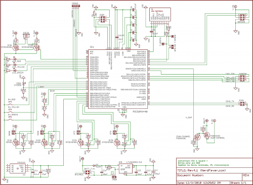
Rev4.1 Schematic (click for full size)
At this point I do have navigation software that (in theory anyway) steers the rocket’s parachute to return back to the launch pad. It seemed to work the one time I’ve had a chance to try it (November 6 – you can read the details in my flight test notes here). It still needs a good deal of tweaking before it’ll be working as well as I want it to – that’s a project for next year’s flying season. One day I’ll get around to posting a full update on the project here.

The code I’m posting today, like the earlier “Rev3” code, does not include the navigation code. But it does include everything else – logging altimeter, parachute deployment, GPS, servo control, etc. Because of the “abuse potential” of the nav code (think of navigating things to places where they ought not to be), I don’t intend to make the nav source code public. Once it’s working well, I might be interested in working with reputable vendors to sell hardware that includes this function, but if I do, it’ll have some protections in place against abuse. The main protection I’m considering is to limit the target location the system will aim for – it has to be a place the unit has physically been since it was powered up (you won’t be able to program in some other location). That way, if you’re not allowed to go somewhere with a handful of blinking rocket electronics, you can’t land the rocket there either. I’d like feedback on this idea. (Yes, anything can be hacked if you put enough effort into it, but my goal is to make it harder to hack the system than for “bad guys” to build their own – there are, after all, books on the subject…)

Anyway, here are the links to the hardware design (schematics only) and software. The deal on rights is exactly the same as with the “Rev3” postings:

Hardware rights: I hereby grant everyone and everything in the universe permission to use and modify this hardware design for any purpose whatsoever. In exchange, you agree not to sue me about it. I make no promises. By using the design you agree that if you’re unhappy the most I owe you is what you paid me (zip). That seems fair.

Here is the schematic for the hardware, in both PDF and as the original CadSoft EAGLE file (see also the ReadMe.txt in there): Rev4.1Schematic.zip

And for the software:

Software rights: I hereby grant everyone and everything in the universe permission to use and modify this software for any NON-COMMERCIAL purpose whatsoever, PROVIDED that you (a) agree not to sue me about it, (b) credit Nerdfever.com as the original source of the software in any publications, and (c) agree that I make no promises and that if you’re unhappy the most I owe you is what you paid me (zip, zero, nada, nothing). Oh, and you agree to USE THIS AT YOUR OWN RISK, that you’re a responsible adult and know that rockets can be dangerous and hurt people if you’re not careful (regardless of whether or not software is involved) so you’ll be careful and will not blame anyone else if you screw up (especially me).

I’ll be very pleased if you leave a comment or drop me an email if you find it useful, but you don’t have to.

For COMMERCIAL use, ask my permission first. If you’re going to make lots of money off my work, I’d like a (oh-so small and reasonable) cut. But I’ve no intention of giving anybody heartache over small amounts – just ask, I think you’ll find me surprisingly easy to deal with.

Here is the the Rev4 code for PIC32, including the Microchip MPLAB IDE project files, just as it appears in the project folder: Rev4.1Code.zip

Although it’s improved in lots of minor ways, the structure of the code is very similar to the Rev3 code, so please use the 6-part posting from last year as a guide to the software. The main UI change from then is that arming/disarming is now done via a reed switch. This lets me arm and disarm the system on the launch pad using a magnet, so I don’t have to make holes in the rocket body for a switch (and worry about lining up the switch with the hole). (Search for “MAGNET” in the code).

Feedback and suggestions for improvement are very welcome. I’m very happy to help out anyone who wants to work with this stuff – just drop me an email or post a comment here.
New “Rev 4” hardware based on the PIC32

This project was mentioned in this month’s Sport Rocketry magazine, so I thought it would be a good time to post a status update on the project.

(If this is your first visit here, have a look here for background as to what the project is about.)

REV4 PCB

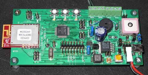
This spring I finished my “Rev4” circuit board, with the PIC32 CPU:

This board also has a USB interface and a Microchip MiWi (ZigBee/IEEE 802.15.4) radio module on board. The “Rev4A” board pictured here is using the GlobalTop FGPMMOPA6 GPS module (the big square thing on the right), which reports at 200 mS intervals. I’ve bought a few of the new PA6B modules (100 mS), but haven’t tried them yet.

The only problem I discovered with the Rev4a hardware was my circuit for driving the piezo buzzer – what I’d meant as an amplifier to make it louder instead shorted it. Happily I’d left enough test jumpers that bypassing the amplifier circuit was nothing more than leaving out 2 berg jumpers and adding a single wire between the pins. So it works and makes noise, but isn’t as loud as I’d like.

I’ve since designed and had fabricated (BatchPCB again) a “Rev4b” PCB that fixes this problem and is about 30% smaller, but I haven’t yet had time to populate and test it.

SOFTWARE

I started by porting over all my old 8-bit (PIC18) code to the PIC32, making improvements along the way. So far I haven’t written any code to drive the radio or the USB port – the hardware is all there, but it doesn’t do anything yet.

I test-flew this board twice on April 24 at the CMASS launch in Amesbury MA. Neither flight was perfect (see Flight Test Notes for flights # 26 and 27) but both were sucessful enough to build some confidence in the stability of the Rev4 hardware and software.

The next project was to either get the telemetry radio and USB working, or to port the navigation code (that will steer the rocket back to the launch site using GPS information) onto the Rev4 hardware.

I tend to like to do things slowly and carefully, one step at a time (perfectionism), so my inclination was to get all the Rev4 hardware working before I started on the final goal of navigation. But the famous words of Michael Faraday when young William Crookes asked him the secret of his scientific success came to mind:

The secret is comprised in three words — Work, finish, publish.

It had been 4 full years since I’d started this project, and I still wasn’t navigating back to the launch site. While it’s true that this is only a hobby project, and I’d been busy in the same period starting a business, raising a family, etc., nonetheless I decided it was time to focus on finishing first, and polishing later.

I’ll bring things up-to-date on that in my next posting. For now I’ll leave you with a video of my most recent flight, from yesterday, July 17:

Don’t buy a lithium battery charger

This post will introduce you to battery charging and tell you how to charge lithium cells using a bench power supply.

Executive summary:

Attach a single lithium cell to the power supply and set it at 4.20 volts and 0.5C. Leave it charging until the current drops to 1/20C. Repeat for all cells in the pack.

I use lithium cells (LiPo, LiIon, etc.) in a lot of my projects – usually surplus cellphone batteries. They have much better energy/volume and energy/weight ratios than other battery types (the next best is NiMH).

But they have a reputation of being “tricky” to charge, and needing a special charger.

Not really.

Put your money into a bench power supply instead of a lithium charger. The power supply will do the charging just as well, and is tremendously useful for other things as well.

You need a constant voltage/constant current (CV/CC) DC power supply. This lets you set a maximum voltage and a maximum current at the same time.

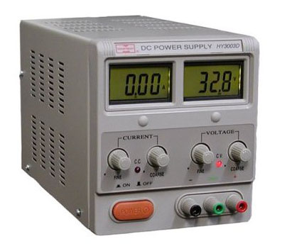
The Mastech 3003D is typical of inexpensive CV/CC bench power supplies. It goes for $110 to $150 online, and is well worth the money. (Mastech is Chinese, but the quality seems OK. Other brands are fine too.)

Batteries 101

Batteries are made up of cells in series. Each cell has a typical voltage that depends on its chemistry – carbon-zinc and alkaline cells are around 1.5 volts, NiCd and NiMH around 1.2 volts, lithium cells around 3.3 to 3.7 volts. Lead-acid cells are around 2 volts.

To get higher voltages, cells are put in series in a battery. Sometimes there’s only one cell in the battery, as with typical lithium “batteries” at 3.6v or so. (Technically these ought to be called just “cells” not “batteries” since there’s only one cell, but people often call them batteries anyway.)

A cell (or battery) has a capacity rated in amp-hours (AH or mAH). For example, an 800 mAH battery can produce 800 mA for 1 hour, or 400 mA for 2 hours, or 8 mA for 100 hours (at the rated voltage) before the battery is drained. In theory.

In practice, cells are usually rated assuming you’ll be draining them over 20 hours. Most batteries produce more energy if you drain them slowly. So, a 5 AH battery can produce something like 250 mA for 20 hours (0.25 * 20 = 5). If you drained it at a rate of 5 amps, it would die before one hour is up.

Also, the voltage gradually drops as you discharge the battery – it starts a little above the rated voltage, then spends most of the time near the rated voltage. When it starts to drop quickly from there, it’s empty.

The current needed to (theoretically) empty the battery in 1 hour is called C.  Charge and discharge currents are given in units of C. For a 800 mAH cellphone battery, C is 800 mA.

Most cells have a maximum discharge current beyond which their performance drops off dramatically. For tiny watch batteries (coin cells), this current is really small – something like 0.002C. (“0.002C” would often be called the “500-hour rate”.) These cells are designed to run a long time at tiny currents. At the opposite extreme are lithium polymer cells designed for high-current uses such as in electric-powered model airplanes. I’ve seen some with a maximum discharge rate of 20C – meaning you can drain them in 1/20 of an hour (3 minutes) reasonably efficiently and without damaging them!

Charging

Most rechargeable battery types can be charged at modest constant currents, without worrying about voltage – something like 0.05 to 0.1C (NiMH, NiCd, lead-acid). So you could charge one of these cell types in 10 or 20 hours with your bench power supply by setting the current to 0.1C or so (500 mA for a 5 AH battery), and just turning the voltage up all the way (so it’s not limited).

(I’m not talking fast charge here – that’s a whole other topic; ask Google about that, not me).

Lithium cells are different. They need to be charged at a constant current until reaching a specific voltage, and then constant voltage. But that’s trivial if you have a CV/CC bench power supply. Read the rest of this entry »

Idea: Intelligent heating tape/sleeve

Edit 2014-11: Nevermind.

Another idea I don’t want to bother thinking about patenting-

How about an intelligent heating tape/sleeve that can be used to keep something (for example, water pipes) permanently above some pre-set temperature?

I imagine a sleeve (possibly surrounded by insulation) that can be put around a water pipe, that contains:

  • A resistive heater
  • A temperature sensor
  • A FET to turn the heater on when the temp falls below the set value (a thermostat)

This would be great to prevent pipes from freezing in the winter in unused rooms (with minimum expenditure of energy). Of course, one can imagine lots of other uses.

I’d power the thing from 12v or so, so nobody gets electrocuted if they cut into it, and to simplify conformance with building codes. You’d probably want the power supply to have a battery backup so it’ll keep working if the power goes out for a while.

If it’s used on a copper pipe, the pipe itself could form the return path, leaving only a single wire to power the thing.

It would have to be segmented so that the stuff can be cut or torn to the desired length. Each segment should have its own thermostat so only the part that needs heat consumes power. And it should be removable without too much trouble, to allow for repair access to the pipe.

Does this thing already exist? Anybody know? (Bill, you reading this?)

Rev3 rocket electronics part 6: isr.c

This is post #6 in a series covering the hardware and software design for my work-in-progress GPS-guided rocket recovery project. The main index to the series of posts is here, and an introduction to the project (a PowerPoint presentation) is here.

This is the last post about the source code, it covers the interrupt service routine (ISR) in isr.c.

On any interrupt, PIC instruction execution goes to memory location 0x0008, where int_vector() causes execution of the interrupt service routine (ISR), isr().

Z-80 SPEEDOMETER

On entry to the ISR, macro PUSH_DEBUG_STATE() (in debug.h) stores the current state of the Z-80 speedometer output SPEEDO in variable pushed_debug_state. This will be restored on exit from the ISR by macro POP_DEBUG_STATE. (BTW, the only thing this has to do with a Z-80 is that’s what I’ve been calling this trick since I first did it on a Z-80 project back in the early ’80s…)

Then the ISR raises the SPEEDO output, because regardless of whether the PIC was busy when the interrupt occurred, it is busy during interrupt servicing.

TIMER1 (RTC) RESET

The ISR then checks PIR1bits.TMR1IF to see if the interrupt was caused by Timer1 overflowing, which generates the RTC tick interrupt. The result is recorded in variable timer1_expired.

If Timer1 did overflow, it is reset by reloading it with the value TMR_START, to trigger the next RTC interrupt at the proper time.

Note that the value of TMR_START (calculated in hardware.h) accounts for the 6 Timer1 tick periods of interrupt latency between Timer1 overflowing and the ISR resetting it. A few NOP instructions are executed before resetting Timer1 to round up this time to a whole number of Timer1 ticks. (The number of NOPs needed was found using Microchip’s PIC18 simulator, included in the MPLAB IDE).

Ideally, the first peripheral to be serviced in the ISR would be the UART receive buffer. At 38,400 bps data bytes from the GPS can arrive as little as 260 microseconds apart, making this interrupt much more time-critical than others. But servicing the UART involves enough conditionals that predicting the exact number of CPU cycles becomes complicated, making it difficult to keep the RTC tick interval accurate.

So instead, the Timer1 interrupt is dealt with first, but just the minimum necessary to reset it. Other tasks that will be performed on the RTC interrupt are postponed until after dealing with GPS data in the UART receive buffer.

RECEIVED DATA

While there is data to be read in the UART receive buffer (PIR1bits.RCIF == TRUE), the data is read out of the UART and stored in NMEAbuffer[] for later parsing by CheckForNewGPSFix() in main().

Before each byte is stored in the buffer, I check:

if (RTC - LastUARTrxRTC > GPS_BURST_PERIOD_MS/RTC_INTERRUPT_INTERVAL_MS)

If so, this means that no data has been received from the GPS for longer than one GPS data burst period. Since the time between data bursts (typically 950 mS or so) is longer than the duration of each burst (typically 50 mS), this indicates that this is the first byte of a new burst, and so the current RTC value is saved in global GPSBurstStartRTC. This is logged with the GPS fix data, to indicate the exact time the fix burst started in terms of the RTC.

Next, the current RTC time is stored in LastUARTrxRTC. This will be used byFlushFlashBufferSafe() and BetweenGPSFixesFor() (both in hardware.c) to detrmine if we are current receiving a GPS data burst, and so if writing to Flash memory needs to be postponed.

If the received byte was a comma, it is converted into a zero. This transforms the NEMA-0183 formatted GPS message (a series of comma separated values) into a series of zero-terminated C strings, to make parsing of the data simpler for CheckForNewGPSFix().

If the overrun flag (RCSTAbits.OERR) was set, this indicates that the UART receive data buffer overflowed (was overrun) and one or more bytes of data were lost. This should never happen, and I don’t think it ever does. But just in case I’m wrong (for example if the CPU clock speed were reduced, the UART baud rate increased, or the ISR changed, this could happen), the flag is reset and the entire line of received data in the buffer is discarded – it’s important to avoid parsing corrupted data. (A wrong GPS fix is much more confusing to the navigation algorithm than a missed one.)

RTC SERVICING

Once the UART has been dealt with, the timer1_expired flag, which was set earlier in the ISR, is checked. If the flag is set, this indicates that the ISR needs to service the Timer1 RTC interrupt, regardless of whether or not there was any received UART data to process.

Macro ServiceBeep() (defined in peripherals.h) is called twice in the RTC handling portion of the ISR – here and again at the end. On each call, this inverts the PIEZO output bit (to the piezo buzzer) if the global variable Beep is set. Since the RTC timer runs at 1 kHz (1 mS intervals), this generates a 1 kHz tone whenever Beep is set – this is used, for example, by BeepOutMaxAltitude() which is called in the FULL state.


Servo pulse generation

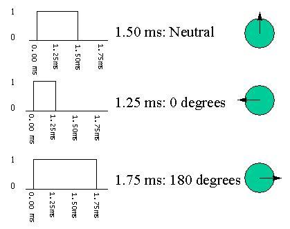
Hobby servo pulse code

Servo control pulses. (Image from Seattle Robotics Society, http://www.seattlerobotics.org/guide/servos.html)


Read the rest of this entry »

Rev3 rocket electronics part 5: stateMachine.c

This is post #5 in a series covering the hardware and software design for my work-in-progress GPS-guided rocket recovery project. The main index to the series of posts is here, and an introduction to the project (a PowerPoint presentation) is here.

In this post I’ll cover stateMachine.c, which implements the finite state machine (FSM) that handles most of the functional logic of the system.

STATE MACHINE

When implementing a state machine, I don’t feel an obligation to observe the constraints of a formal FSM of the kind taught in schools, where all functionality happens in state transitions.

Instead, I treat each state as a system mode. There are state entry actions and state exit actions, but while in each state the system also has a distinct behavior. While I could draw a state diagram, I’ve never bothered – the system is simple enough that it’s unnecessary, and the diagram wouldn’t capture much of the important behavior of the system.

The state machine is run one step by a call to StateMachine() from main(), which happens once each time through the main loop.

Each of the six states, IDLE, ARMED, TIMEDLAUNCH, FLIGHT, FULL, and TEST, (all defined in stateMachine.h) has an associated “state function” that implements the system behavior for that state. Each state also has an associated entry function, which can be called by state functions to cause the system to transition to a new state.

The state functions take and return no parameters and have the same names as the state symbols, but in lowercase:

  • void idle(void);
  • void armed(void);
  • void timedlaunch(void);
  • void flight(void);
  • void full(void);
  • void test(void);

The entry functions also take and return no parameters and are named based on the state they enter:

  • void enterIDLE(void);
  • void enterARMED(void);
  • etc.

The current state and sub-state are stored in global variables State and Substate.

STATE TRANSITIONS

When conditions warrant, a state function will cause a transition to a different state by calling the appropriate entry function, which will change the global variables State and Substate to reflect the new state, as well as performing any entry actions needed to configure the system for the new state.

A flag, stateTransitionInProgress, is reset to FALSE on entry into StateMachine(). Each entry function starts by verifying that this flag is FALSE, and if so, setting it TRUE. If the flag is not FALSE on entry, this indicates that the FSM has already transitioned to a new state, and therefore the call to the entry routine is invalid. In that case, the entry routine is aborted and the state remains unchanged.

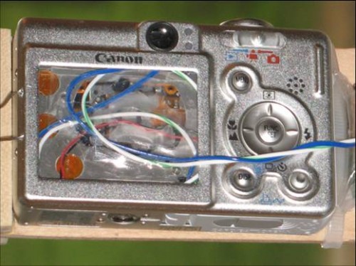
Wiring to camera shutter button

This eliminates the possibility of a subtle bug which could occur if, once a state function calls an entry function (to transition to a new state), later logic in the same state function tries to put the system into a different new Read the rest of this entry »

Rev3 rocket electronics part 4: main.c

This is post #4 in a series covering the hardware and software design for my work-in-progress GPS-guided rocket recovery project. The main index to the series of posts is here, and an introduction to the project (a PowerPoint presentation) is here.

This post covers main.c, which has just one function in it, main(), the program that runs on power-up or reset.

INITIALIZATION

main() starts by calling SetupHardware() in hardware.c, which initializes the PIC internal registers. Many of the values used to initialize things are computed from macros based on tweaks.h. OSCCON is set to control the CPU clock frequency, INTCON and PIE are set to enable the global, peripheral, UART, and Timer1 interrupts. SetupHardware() has comments on how Timer1 is used to generate the servo control pulses, which I won’t repeat here, but see my discussion of this in my posting about the ISR.

Next 16-bit timers Timer1 and Timer3 are initialized to run at a rate of 250 kHz (1/32 of the 8 MHz CPU clock) and started.

Then, the I/O ports are setup (direction and weak pullups on Port B), CVRef is setup to produce a reference voltage and an analog comparator is configured for level-conversion of the incoming received GPS data (see the hardware description for details of that) and an ADC is setup to read AN1 for the pressure sensor.

Finally Timer2 (TMR2) and CCP2 are setup to produce the 47 kHz square wave modulation for the camera control IR pulses (again, see the hardware description). Finally, the magnetic compass is initialized, if the compilation switch COMPASS is defined (it isn’t, now).

main() then turns on all 3 LEDs (to indicate that the system is powered up and running), sets the servo to the middle position, initializes the leaky integrator values used to smooth out pressure sensor readings, calls InitGPS() to send GPS commands to set the desired baud rate and mode (38,400 bps, $GPRMC and $GPGGA messages only), and initializes the state machine.

The last thing main() does before entering the main (endless) software loop is:

nextRTC8 = RTC8 + LOOP_PERIOD;

This deserves some explanation, as I use this technique a lot (mostly in stateMachine.c – see next post).

Global 32-bit variable RTC holds a count of real-time-clock (RTC) interrupts since power-up. Macros RTC24, RTC16, and RTC8 (all in globals.h) return the low-order 24, 16, and 8 bits of this count (respectively – note that the C18 compiler supports 24 bit wide variables).

This statement assigns the modulo-256 (8 bit) sum of the lower 8 bits of this count (RTC8) and a constant called LOOP_PERIOD to an 8-bit variable called nextRTC8.

LOOP_PERIOD is defined in tweaks.h as the number of RTC ticks in 40 milliseconds (25 Hz). So nextRTC8 represents the future value RTC8 will have 40 milliseconds from now.

By comparing nextRTC8 to RTC8, we can easily determine whether the 40 milliseconds have expired. Macros YET8(), YET16(), YET24(), YET32() and NOTYET8(), NOTYET16(), NOTYET24() and NOYET32() (all in globals.h) implement this comparison and allow for the possibility that by the time the comparison is made (between nextRTC8 and RTC8), RTC8 might have already moved on to a later value (if the check isn’t performed between each tick of the RTC interrupt).

So, when later in main() we say:

while (NOTYET8(nextRTC8))

we will continue in the while() loop as long as the current time has not yet reached future time “nextRTC8” (40 milliseconds from the time we set the value of nextRTC8).

Of course, nextRTC8 and RTC8 are only 8 bits wide, so the time represented in nextRTC8 had better not be more than 127 RTC ticks in the future (127 mS). If you need to deal with longer time periods than that, you’ll have to use one of the wider versions – RTC16, RTC24, or RTC32.

MAIN LOOP

The main loop of the program starts with while(1) and runs once every 40 milliseconds (25 Hz). All system functions are driven by this loop, except what the interrupt service routine (ISR) does.

A 32-bit variable CycleCount is incremented each time through.

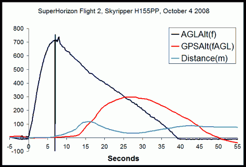
Graph from logged pressure altitude & GPS data. GPS altitude is useless – data is heavily damped, resulting in a lag of 12 seconds or so. But the GPS position data is not too bad.

GPS

Then CheckForNewGPSFix() is called (from nmeaGps.c).  Any incoming data from the GPS has been received by the ISR and placed in a small text buffer, NMEAbuffer[]. CheckForNewGPSFix() looks at the text buffer to see if a complete message has been received from the GPS. If so, it parses the message. ($GPGGA or $GPRMC; these are the only two messages that are handled.) Read the rest of this entry »

Rev3 rocket electronics part 3: Source code summary

This is post #3 in a series covering the hardware and software design for my work-in-progress GPS-guided rocket recovery project. The main index to the series of posts is here, and an introduction to the project (a PowerPoint presentation) is here.

This post is an introduction to the source code. (Which can be downloaded from my last post.)

OVERVIEW OF SOURCE FILES

The software consists of the following C source files:

  • main.c – hardware init and main program loop
  • stateMachine.c – finite state machine (most functionality is here)
  • globals.c – global variables
  • isr.c – interrupt service routine
  • hardware.c – hardware abstraction wrappers
  • peripherals.c – higher-level (than hardware.c) peripheral control
  • nmeaGps.c – reads and parses NMEA-0183 standard format GPS data
  • logging.c – logging of flight status data to Flash memory
  • compass.c – drives Honeywell HM55B magnetic compass (no longer used)

and the following header files:

  • tweaks.h – main “tweakable” parameter file and compilation switches
  • stateMachine.h – defines state values and prototypes for stateMachine.c
  • globals.h – prototypes for globals.c, generally useful macros
  • hardware.h – symbol definitions for hardware abstractions, prototypes for hardware.c
  • peripherals.h – peripheral-related macros and constants, prototypes for peripherals.c
  • nmeaGps.h – data structure for GPS fixes, prototypes for nmeaGps.c and related constants
  • logging.h – data structures for flight data logging, prototypes for logging.c
  • compass.h – hardware abstractions for compass, prototypes for compass.c
  • debug.h – macros to support “Z-80 Speedometer”
  • djllib.h – variable type definitions, standard constants, misc. macros

In addition there is the Microchip header file pic18f26k20.h and the linker file 18f2620i.lkr. Neither of these are my work – they are unmodified from Microchip.

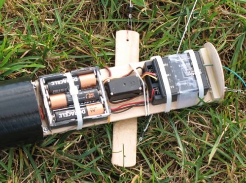
Servo arrangement after successful radio-controlled landing. To fit in the rocket, the servo arm stays at an extreme setting until after parachute deployment.

SYMBOL NAMING CONVENTIONS

These are the naming conventions I use for function and variable names:

Function scope Variable scope Convention 1st character
n/a Block (local) lower_case_ABBR_excepted_underscore_delimited Lowercase
File (normal) File mixedCaseDelimitedABBRexcepted Lowercase
Global (exported) Global MixedCaseDelimitedABBRexcepted Uppercase
Macro Macro ALL_CAPS_UNDERSCORE_DELIMITED Uppercase
n/a Typedef ALL_CAPS_UNDERSCORE_DELIMITED Uppercase

Also, a name with a leading underscore, for example _name(), indicates a “hidden” function or variable which is not meant for general use. Usually it’s a component of some other function that is meant to be used on a normal basis. (See __waitloop_internal() in hardware.c and #define wait() in hardware.h for an example.)

WHERE TO START

If you want to have a look at the software with an eye to modifying it, I suggest you start with a quick skim of the following files (in this order): Read the rest of this entry »

Rev3 rocket electronics part 2: Software overview

This is post #2 in a series covering the hardware and software design for my work-in-progress GPS-guided rocket recovery project. The main index to the series of posts is here, and an introduction to the project (a PowerPoint presentation) is here.

This post will introduce the software at a high level.

I’ll start with a rough outline of the software architecture and functional spec for the Rev3 hardware/software system.

I say rough because, like most one-man projects, things evolve without necessarily being thoroughly documented. That said, the code is heavily commented (and the comments are up-to-date), so it shouldn’t be too difficult to follow what is going on.

This post will give you an idea of what to expect, but you really need to read the source code to fully understand what is going on.

Regarding rights: My attitude toward the software is a little different than for the hardware. I’m posting all the source code and these comments to help people understand it, and I want to encourage people to use and modify it. However, much hard-won experience is represented in the software and it has a lot more general utility, even outside of rocketry.

So here’s the deal – I hereby grant everyone and everything in the universe permission to use and modify this software for any NON-COMMERCIAL purpose whatsoever, PROVIDED that you (a) agree not to sue me about it, (b) credit Nerdfever.com as the original source of the software in any publications, and (c) agree that I make no promises and that if you’re unhappy the most I owe you is what you paid me (zip, zero, nada, nothing). Oh, and you agree to USE THIS AT YOUR OWN RISK, that you’re a responsible adult and know that rockets can be dangerous and hurt people if you’re not careful (regardless of whether or not software is involved) so you’ll be careful and will not blame anyone else if you screw up (especially me).

I’ll be very pleased if you leave a comment or drop me an email if you find it useful, but you don’t have to.

For COMMERCIAL use, ask my permission first.  If you’re going to make lots of money off my work, I’d like a (oh-so small and reasonable) cut.  But I’ve no intention of giving anybody heartache over small amounts – just ask, I think you’ll find me surprisingly easy to deal with.

That said, here is the the code, including the Microchip MPLAB IDE project files, just as it appears in the project folder: Rev3Board.zip

You may find it handy to look at the code when reading this introduction, although I’ll save the gory details for later posts.

SOFTWARE ARCHITECTURE

There is no real-time operating system (RTOS) – no operating system of any kind.

All the code is in C running directly on the “naked” hardware. In my experience RTOSes are very rarely useful in simple-to-moderate complexity embedded systems. Instead, they tend to add a needless layer of complexity and overhead that serves to obscure what is really going on. (RTOSes do have a proper place, I just think they’re over-used.)

I also don’t use any of Microchip’s hardware interface libraries. Instead, I control the hardware directly according to the PIC datasheet. I prefer to know and control what is really going on, and learning how to control the hardware doesn’t take much longer than learning how to use the library functions.

Some will say this makes the code less portable to other MCUs, but I prefer to have a solid understanding of what the code is doing so that I can intelligently port it when needed. In my view this is less risky than relying on the compatibility of “black-box” libraries which, in my experience, often disappoint. I do isolate all the hardware interface functions in a single module (see hardware.h and hardware.c).

As you read the code, you’ll see that I compute many constant values in the C pre-processor. (For example, see #define FLASH_BUFFER_ROWS and #define MS_TO_UTICKS  in hardware.h.)  I find this helps clarify how the constants are calculated, as well as reducing code size.

CONDITIONAL COMPILATION (#ifdef)

I make some use of conditional compilation in the code. The major compilation switches are all set (or not) in file tweaks.h. Most of them relate to the presence or absence of various bits of hardware (magnetic compass, GPS models, particular servos, etc.)

The compilation flags __DEBUG and ICD2 disable the “red” button input (symbol SW_RED) for debug builds. This button shares a pin with the ICD2 reset line, so including __DEBUG will include the compilation switch ICD2, which prevents the “red” button from being used (and therefore resetting the CPU). When these switches are defined, the compiler will generate a couple of warnings about code that doesn’t do anything – this is intentional. Read the rest of this entry »

Rev3 rocket electronics part 1: Hardware

This is post #1 in a series covering the hardware and software design for my work-in-progress GPS-guided rocket recovery project. The main index to the series of posts is here, and an introduction to the project (a PowerPoint presentation) is here.

In this post I’ll cover the hardware design, including the schematic, board layout, and Eagle PCB files from my “Rev3” hardware of March 2007. (That’s the most recent version I have working as of this writing.)  This post is also a good starting point even if you’re mainly interested in the software – as a tightly integrated system, an understanding of the hardware is key to the software as well.

About rights: I hereby grant everyone and everything in the universe permission to use and modify this hardware design for any purpose whatsoever. In exchange, you agree not to sue me about it. I make no promises. By using the design you agree that if you’re unhappy the most I owe you is what you paid me (zip).  That seems fair.

If you find this useful, I’ll be pleased if you drop me a note or leave a comment here (just so I know it’s been helpful to someone) and if you give credit to Nerdfever.com for the design in any publications. But you don’t have to.

The board was designed in Eagle PCB, which is available in a free “light” edition, limited to non-profit use and 2-layer boards of not more than 4.0 x 3.2 inches. (Sufficient for this board.) Eagle takes some getting used to, but works well.

If you want to modify my design, here are the Eagle PCB files for the schematic and board: Autopilot_r3.zip

This hardware has made many successful flights, and supports the following features:

  • PIC18F2620 MCU (programmable in C)
  • GPS interface
  • Drives a hobby servo (to steer the parachute)
  • Pressure altimeter (good to about 2 feet precision)
  • Triggers parachute deployment at apogee
  • Able to log flight data in flash memory
  • Drives an in-flight digital camera
  • Piezo speaker output
  • 3 push-buttons, 3 LEDs

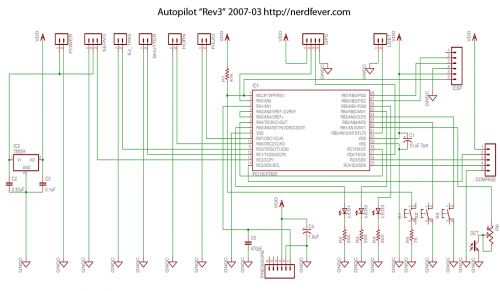
Figure 1 shows the schematic:

Rev3 Schematic

Fig. 1 - Rev3 schematic

A few comments about the circuit are in order.

MCU

The MCU is a PIC18LF2620. It has 3968 bytes of RAM and 64 kbytes of Flash memory, which is available for both program space and logging of flight data. It will run at up to 8 MHz off the PIC’s internal oscillator – I don’t use an external crystal.

Interestingly, these specs are very similar to those of the Apollo Guidance Computer. Except that the PIC is a single 28-pin chip, costs about $4, and draws only a couple of milliamps.

You can program the PIC using Microchip’s free C18 compiler and free MPLAB IDE environment – those are what I recommend.

GPS

The board was designed to interface with a GlobalSat EM-406 GPS using a serial UART interface. I’ve used others (see tweaks.h for a list); it will probably work fine with any serial-interface GPS.

The PIC transmits to the GPS on pin 17 of the PIC (TX).

Note that pins 4 and 5 of the PIC are tied together, and pin 6 (C1OUT)  is tied to pin 18 (RX). This is part of a no-hardware level-shifting scheme that allows the 5v PIC to read data from the EM-406 GPS, which outputs at 0v/2.85v. Read the rest of this entry »