This is post #6 in a series covering the hardware and software design for my work-in-progress GPS-guided rocket recovery project. The main index to the series of posts is here, and an introduction to the project (a PowerPoint presentation) is here.
This is the last post about the source code, it covers the interrupt service routine (ISR) in isr.c.
On any interrupt, PIC instruction execution goes to memory location 0x0008, where int_vector() causes execution of the interrupt service routine (ISR), isr().
Z-80 SPEEDOMETER
On entry to the ISR, macro PUSH_DEBUG_STATE() (in debug.h) stores the current state of the Z-80 speedometer output SPEEDO in variable pushed_debug_state. This will be restored on exit from the ISR by macro POP_DEBUG_STATE. (BTW, the only thing this has to do with a Z-80 is that’s what I’ve been calling this trick since I first did it on a Z-80 project back in the early ’80s…)
Then the ISR raises the SPEEDO output, because regardless of whether the PIC was busy when the interrupt occurred, it is busy during interrupt servicing.
TIMER1 (RTC) RESET
The ISR then checks PIR1bits.TMR1IF to see if the interrupt was caused by Timer1 overflowing, which generates the RTC tick interrupt. The result is recorded in variable timer1_expired.
If Timer1 did overflow, it is reset by reloading it with the value TMR_START, to trigger the next RTC interrupt at the proper time.
Note that the value of TMR_START (calculated in hardware.h) accounts for the 6 Timer1 tick periods of interrupt latency between Timer1 overflowing and the ISR resetting it. A few NOP instructions are executed before resetting Timer1 to round up this time to a whole number of Timer1 ticks. (The number of NOPs needed was found using Microchip’s PIC18 simulator, included in the MPLAB IDE).
Ideally, the first peripheral to be serviced in the ISR would be the UART receive buffer. At 38,400 bps data bytes from the GPS can arrive as little as 260 microseconds apart, making this interrupt much more time-critical than others. But servicing the UART involves enough conditionals that predicting the exact number of CPU cycles becomes complicated, making it difficult to keep the RTC tick interval accurate.
So instead, the Timer1 interrupt is dealt with first, but just the minimum necessary to reset it. Other tasks that will be performed on the RTC interrupt are postponed until after dealing with GPS data in the UART receive buffer.
RECEIVED DATA
While there is data to be read in the UART receive buffer (PIR1bits.RCIF == TRUE), the data is read out of the UART and stored in NMEAbuffer[] for later parsing by CheckForNewGPSFix() in main().
Before each byte is stored in the buffer, I check:
if (RTC - LastUARTrxRTC > GPS_BURST_PERIOD_MS/RTC_INTERRUPT_INTERVAL_MS)
If so, this means that no data has been received from the GPS for longer than one GPS data burst period. Since the time between data bursts (typically 950 mS or so) is longer than the duration of each burst (typically 50 mS), this indicates that this is the first byte of a new burst, and so the current RTC value is saved in global GPSBurstStartRTC. This is logged with the GPS fix data, to indicate the exact time the fix burst started in terms of the RTC.
Next, the current RTC time is stored in LastUARTrxRTC. This will be used byFlushFlashBufferSafe() and BetweenGPSFixesFor() (both in hardware.c) to detrmine if we are current receiving a GPS data burst, and so if writing to Flash memory needs to be postponed.
If the received byte was a comma, it is converted into a zero. This transforms the NEMA-0183 formatted GPS message (a series of comma separated values) into a series of zero-terminated C strings, to make parsing of the data simpler for CheckForNewGPSFix().
If the overrun flag (RCSTAbits.OERR) was set, this indicates that the UART receive data buffer overflowed (was overrun) and one or more bytes of data were lost. This should never happen, and I don’t think it ever does. But just in case I’m wrong (for example if the CPU clock speed were reduced, the UART baud rate increased, or the ISR changed, this could happen), the flag is reset and the entire line of received data in the buffer is discarded – it’s important to avoid parsing corrupted data. (A wrong GPS fix is much more confusing to the navigation algorithm than a missed one.)
RTC SERVICING
Once the UART has been dealt with, the timer1_expired flag, which was set earlier in the ISR, is checked. If the flag is set, this indicates that the ISR needs to service the Timer1 RTC interrupt, regardless of whether or not there was any received UART data to process.
Macro ServiceBeep() (defined in peripherals.h) is called twice in the RTC handling portion of the ISR – here and again at the end. On each call, this inverts the PIEZO output bit (to the piezo buzzer) if the global variable Beep is set. Since the RTC timer runs at 1 kHz (1 mS intervals), this generates a 1 kHz tone whenever Beep is set – this is used, for example, by BeepOutMaxAltitude() which is called in the FULL state.

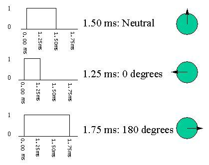
Servo control pulses. (Image from Seattle Robotics Society, http://www.seattlerobotics.org/guide/servos.html)
After incrementing the global RTC variable, the ISR next checks if it is time to start a new servo control pulse.
The position of a standard hobby-type servo is proportional to the duration of each of a series of pulses, sent at intervals of about 20 mS. As shown in the figure above, a pulse duration of 1.5 milliseconds typically positions the servo in the center of its range. The leftmost position is reached with a pulse length of around 0.5 mS, and the rightmost position with a pulse length of around 2.5 mS. The left and right position limits vary somewhat from servo to servo (see hardware.h for the actual limits on a few servos I tried), but 1.5 mS is consistently close to the center position.
The hardware initialization routine SetupHardware() configured both 16 bit Timer1 (used to generate the 1 mS RTC interrupts) and 16 bit Timer3 to count at the same rate – 1 count for every 32 system CPU clocks (FOSC/4 with a 1:8 prescale). Once configured, these timers count automatically in hardware, without software intervention. For example, at 8 MHz these timers increment at a rate of 250.0 kHz (4 microseconds). I call each of these Timer1/Timer3 increment events a “microtick” (abbreviated UTICK), to distinguish them from the ordinary 1 mS “ticks” of the RTC.
The function SetServoPos() in hardware.c (not part of the ISR) can be called to set the servo position anywhere from its leftmost position (0) to its rightmost position (255). SetServoPos() uses the desired position and macro MS_TO_UTICKS() in hardware.h to calculate the servo pulse duration needed, in microticks, and stores the result in global variable ServoPulseLengthUTicks. Interrupts are disabled while writing to ServoPulseLengthUTicks to force this operation to be atomic.
The ISR starts a new pulse every 20 milliseconds (the standard interval – most servos will accept somewhat more or less frequent pulses as well). The pulse duration is controlled by PIC Capture/Compare Module CCP1, which is driven off of Timer3.
Static local variable ticks_till_servo_pulse is decremented in the ISR each time the RTC ticks (every 1 mS). After 20 ticks (SERVO_PULSE_INTERVAL / RTC_INTERRUPT_INTERVAL), it reaches zero and a new servo pulse is generated.
To do that, first ticks_till_servo_pulse is set back to 20, then Timer3 (which was configured in SetupHardware() to run at the same rate as Timer1), is turned off and reset to zero.
Next, CCP1 is configured to end the servo pulse after the proper duration. The CCP1 hardware will monitor the value of Timer3, and drop the SERVO output pin (ending the pulse) when Timer3 reaches the value programmed into CCPR1H and CCPR1L. These hardware registers are loaded with the value of ServoPulseLengthUTicks, previously calculated by SetServoPos().
Then, the CCP1 module is configured – it is put in “compare mode” (compare CCPR1 to Timer3 value), with output pin (SERVO) initially high, and to force the pin low when Timer3 reaches the CCPR1 value. Finally, Timer3 is started.
At that point the SERVO pin will go high, starting the servo pulse. It will stay high until Timer3 counts the number of microticks calculated by SetServoPos(). Then the CCP1 hardware will force the SERVO pin low, ending the pulse without any software action.
Camera IR control
The lines:
if (IRCode & 1)

IR_ON;

else

IR_OFF;
IRCode /= 2;
are all that is needed to transmit infrared control signals to the camera.
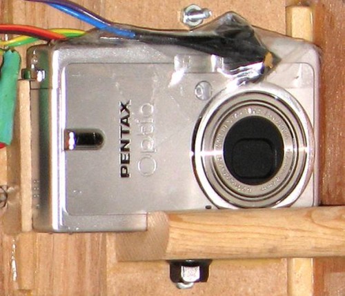
The routine TakePicture() loads 32-bit global variable IRCode with the command message to be sent to the camera. On each 1 mS tick of the RTC, the ISR executes macro IR_ON or IR_OFF (both defined in hardware.h) depending on the least significant bit of IRCode. IR_ON turns on the 47-kHz modulated IR output, IR_OFF turns it off. Then, the value IRCode is shifted one bit to the right.
The result is that the 32 bit value loaded into IRCode by TakePicture() becomes a series of 1 mS infrared on or off pulses (with the ON pulses modulated at 47 kHz). This code commands the camera to take a picture.
ISR EXIT
To finish handling the Timer1 interrupt, the interrupt flag is reset (PIR1bits.TMR1IF = 0).
Finally, POP_DEBUG_STATE() restores the original state that the SPEEDO pin had when entering the ISR.

