It all started with a pair of Radio Shack Optimus Pro 7 bookshelf loudspeakers I picked up on eBay for a song.
These little speakers sound fantastic for their size, and at one time you could get them new at Radio Shack really cheap – I’ve been using a pair of white Pro 7AVs (the magnetically-shielded version) since the mid-90s as my PC desktop speakers.
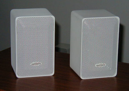
Pro 7AV speakers (photo courtesy of Wade’s Audio and Tube)
One day I was procrastinating by surfing eBay, ran across a black pair that looked nice, put in a bid, and soon had them in my basement, waiting for a project to use them.
Then I noticed the existence of low-cost TriPath TA2020-based amplifiers like this very popular one from Lepai. These things get fantastic reviews – the TA2020 uses PWM amplification and its distortion sounds like tube (valve) amplifier distortion. And audiophiles have been paying outrageous prices for tube amplifiers ever since tubes went out of style. Yet these TA2020 amplifiers go for 20 bucks! (And, yes, I know putting “audiophile” and “outrageous prices” in the same sentence is a bit redundant, but I’m not getting into that now.)
You may have figured out by now that I just can’t resist cheap things that deliver ridiculous value – it’s a character flaw. So combine the cheap-but-great loudspeakers with the cheap-but-great amplifier, and I just had to do something with them.
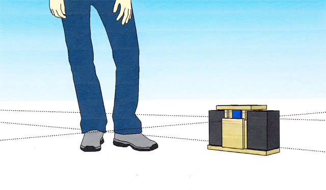
I decided to make a set of portable Bluetooth speakers. I’ve bought a few different Bluetooth loudspeakers and they all sound terrible to my ears; even the way-overpriced Bose ones sound bad to me (and I’m too cheap to pay that much anyway). So I thought I’d make my own.
There’s a guy Arjen Helder in Shenzhen (arjenhelder_electronic on eBay) who makes very well-reviewed TA2020 amplifiers, and he has a model “TA2024 MKV Bluetooth” with the Bluetooth module already built in. So 20 pounds sterling later (“Approximately US $30.35”), I’ve got one of those and I’m ready to start.
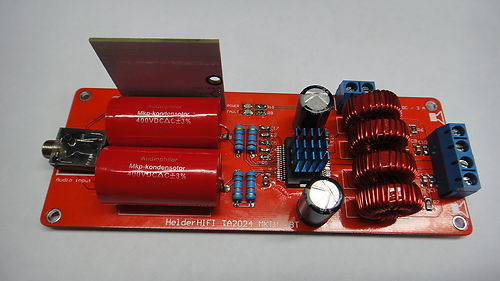
Helder HiFi TA2024 MKV Bluetooth amplifier
I wanted my speaker set to be portable, so that means they need a battery, and I happened to have an old 12V 5AH AGM battery around. Since the amplifier runs on 12VDC, that seemed a good fit. And I had a spare Harbor Freight 12V charger too ($9.99; did I mention I’m cheap?), so I figured I’d use that to both charge the battery and power the amp while it’s plugged in.
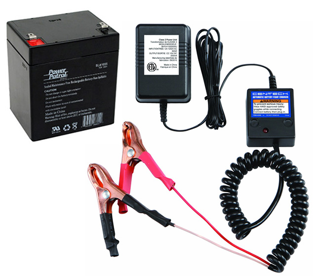
12V 5AH SLA battery and $9.99 Harbor Freight charger. (Not quite to the same scale…)
(Yes, I’m going to get to OpenSCAD. Be patient!)
So now I had most of the bits and pieces, and needed to come up with a design for the speaker set. I wanted a handle (to make it more portable; the speakers and lead-acid battery are heavy) and a place to wind some extra speaker cable, so I could separate the speakers for better stereo. That meant the speakers had to be held in a way that allows removing them, yet at the same time I didn’t want them to fall out by accident while carrying the set by the handle.
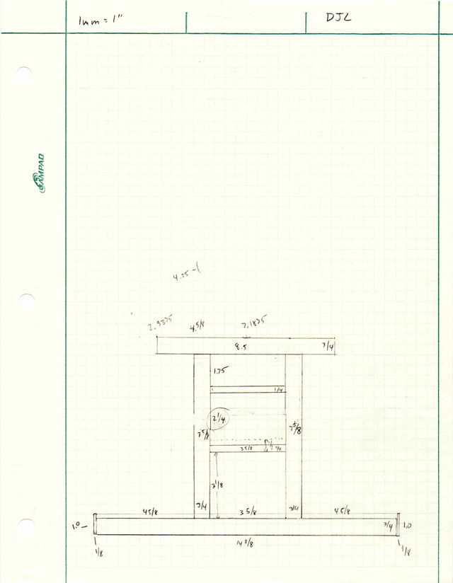
So I started sketching on paper. Here’s one of the earlier sketches:
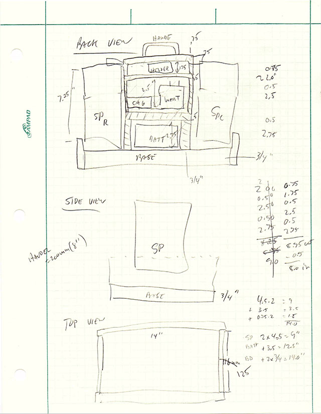 OK, so I’m not a good artist.
But the important thing was to get the dimensions right. I wanted it to be compact, but have room for all the pieces. (BTW, I hate using inches and fractions as much as anyone, but I’m in the US and lumber here only comes in those dimensions, so I’m stuck with them.)
As I made each sketch, I realized there were opportunities for improvement (perfectionism is another of my character flaws), so first I’d scratch things out, then at some point I’d start a whole new sketch:
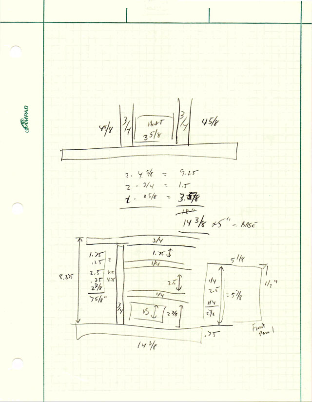
and another:
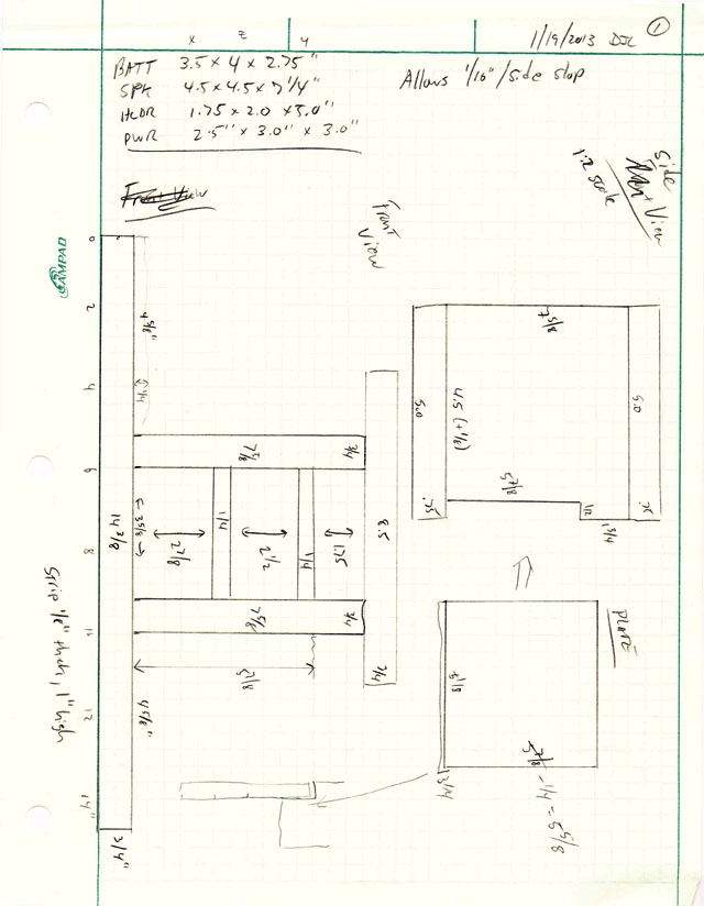
and another:
Etc.
This was frustrating. Any little change cascaded all across the design, and it was easy to make a mistake in calculating dimensions.
So I decided to see if I could find some simple CAD program to help. I spent some time communing with Google, and decided that SketchUp (ex-Google SketchUp, now owned by Trimble) was the way to go.
I spent a few hours learning to use it, and made moderate progress getting my design into the program:
How far I got with SketchUp
However, I found it very difficult to transfer the dimensions from my paper sketches into SketchUp; there didn’t seem to be any direct way to force SketchUp to size things exactly, or to position parts at particular offsets with respect to other parts. SketchUp, although it’s far simpler than most “serious” CAD programs, still has a long learning curve, and it didn’t seem very well suited to the kind of engineering drawings I was trying to do. I could easily get things close, but couldn’t get them exact (I suppose there must be a way to do it, but I didn’t figure it out).
After trying and getting stuck for a few hours, I went looking for a better solution.
And that’s when I found OpenSCAD.
[To be continued in Part 2…]