The future of video conferencing?

For years I’ve been saying that video conferencing as-we-know-it will never get beyond the sub-5% penetration of the business world that it’s been in for the last 20 years – let alone the mass-market. (For my reasons in some detail, see my slides from 2008).

This (see video below) is the most encouraging thing I’ve seen in years. It’s far from production-ready, but this is the most practical way of really solving the all-important issues of knowing who-is-looking-at-whom, pointing, and eye contact that I’ve yet seen. (I don’t think telepresence systems do a sufficiently good job, even ignoring their cost. And this solution is cheap.)

Wait for the end where he steps into the view – until then I thought it was a single frame; it’s not – it’s done in real time on cheap hardware.

The core idea here – if you haven’t figured it out already – is to have two or more cameras looking at the same scene from different angles. To make things easier, he’s also got two Microsoft Kinects (one for each camera) directly reporting depth information. With a little geometry he can figure out the relative position of each object in the scene, and make a “virtual camera” that produces an image as it would be seen from any viewpoint between the cameras.

I mentioned this video to some friends on a mailing list, and got a couple of responses questioning the whole idea that there is a “problem” with current video conferencing technology. Supposedly lots of people already use video telephony – there is Skype video, Google, NetMeeting, AIM, Polycom, Tandberg, telepresence systems, and and the iPhone 4’s front-facing camera, so isn’t practical video communication already here?

Of course. I use video calling too – for example to chat with my son in college. But it’s very – deeply – unsatisfying in many ways, and works even worse in multi-point situations (3 or more sites in the call) and when there is more than one person at each site. And I think that is limiting use of the technology to a tiny fraction of what it would be if video communication worked the way people expect.

Consider the best-case situation of a simple point-to-point video call between two people – two sites, one person on each end. In many ways today’s video is a good improvement over ordinary telephony. The biggest problem is lack of eye contact, because the camera viewpoint is not co-located with the image of the far-end person’s eyes on the display.

Look at George Jetson and Mr. Spacely, below. They most definitely have eye contact. This interaction between boss and employee wouldn’t be the same without it. But we, the viewer, don’t have eye contact with either of them. And both of them know it.

We also expect, looking at the scene, that Mr. Spacely (on the screen) has peripheral vision – he could tell if we were present in the room with George. We feel he could look at us if he wanted to.

This is how people expect, and want, video communication to work. The artist who drew this scene knows all this without being told. But this is not how today’s video works.

George Jetson & Mr. Spacely (The Jetsons, Hanna Barbera, date unknown)

Eye contact is a profoundly important non-verbal part of human social communication. Our brains are hardwired to know when we’re being looked in the eyes (even at amazing distances). Some people think human eyes have evolved not just to see, but also to be seen by other people. Lots of emotional content is communicated this way – dominance/submission, aggression/surrender, flirting, challenge, respect, belief/unbelief, etc. Without eye contact, video communication often feels too intimate and uncomfortable; because we can’t tell how the other person is looking at us, we have to assume the “worst case” to some extent. I think this is why video today, to the extent it is used for communication, is mostly used with our intimate friends and family members, where there is a lot of trust, and not with strangers.

Consider Jane Jetson, below, chatting away on the videophone with a girlfriend on a beach somewhere. We do this all the time with audio-only mobile phones, so people expect that they ought to be able to do the same with a videophone. This is reflected in fiction. So, look – where is the camera on the beach? Where is the display on the beach? It certainly isn’t in the hand of Jane’s friend – we can see both her hands. It’s not on the beach blanket. Where is it? Jane is sitting off to one side of the display; not in front. If she were using a contemporary video conferencing system, what would her friend on the beach see? Where is the camera on Jane’s end? Would Jane even be in the field of view? Look at Jane’s eyes – she’s looking at the picture of her friend on the screen, not at a camera. Yet they seem to have eye contact. How can this be? (Answer: With today’s equipment, it can’t.)

The Jetsons (Hanna-Barbera, 1962)

Things get much worse when you move to multi-point communication – where there are 3 or more sites in the call, and usually more than one person at each site. Then, you can’t tell who is addressing whom, who is paying attention, etc.

My perspective on this comes from having worked in the video conferencing industry for 15 years (not anymore, and I’m glad of that). That industry has been selling conferencing equipment to large organizations since the mid 1980s. The gear was usually sold on the basis of the costs to be saved from reduced travel – which mostly didn’t happen. Despite the fact that almost every organization bigger than a dozen people or so has at least one conference room for meetings, less than 2% of those conference rooms, worldwide, are equipped for video conferencing even today.

This state of affairs is very different from what anyone in the industry expected in the 90s.

All the things that the Jetsons artist – and typical consumers – so easily expect to “just work”, don’t work at all in the kind of video systems we build today. And that is a large part of why video communication is not nearly as sucessful or widespread as it might be.

These are not the only problems with today’s video systems (for a longer list, see my slides), and virtual camera technology won’t solve all of them. But it may solve some of the most important ones, and it’s a great start. Here’s another demo from the same guy:


This guy – Oliver Kreylos at UC Davis, judging by his web page – is by no means the first to play with these ideas – I saw a demo of something very similar at Fraunhofer in Berlin around 2005, and recall seeing papers describing the same thing posted on the walls of the MIT AI lab way back in the 1980s (back then they were doing it with still images only – the processing power to do video in real-time didn’t yet exist).

What is new is the ability to do it in a practical way, in real-time, with inexpensive hardware. He’s using Microsoft Kinects – which directly output depth maps – to vastly simplify the computation required and, I think, improve the accuracy of the model. Obviously there is a fair amount of engineering work still needed to go from this demo to a salable conferencing system. But I think all the key principles are at this point well understood – nothing lies in the way but some hard work.

To my many friends still in the video conferencing industry – watch out for this. It won’t come from your traditional competitors – well-established companies usually don’t innovate other than minor improvements on what they already do. For something really new, they wait for somebody else to do it first, then they respond. Some small start-up, without people invested in the old way of doing things (or a desperate established firm) will probably do it first. (Why not you?)

Suppose you want to build a classical multipoint video conferencing system (VCS) – you have 3 or more sites, each with multiple people present, for example around a conference table. I think you can use this technology to make a conferencing system that feels natural and allows for real eye contact, pointing, and many of the other things that are missing from today’s VCS and “telepresence” systems.

How would such a system work?

All you need to do is send 2 or 3 video streams plus the depth data. Then each receiver can generate a virtual camera viewpoint anywhere between the cameras, so each viewer can see from a unique viewpoint.

Then if you co-locate the virtual camera positions with the actual (relative) display positions, you have real eye-contact and pointing that (should) work.

And if you have a 3D display, it shouldn’t be too hard to even have depth. (But I think it’ll work pretty well even with regular 2D displays.)

You need to send to the far-end:

  • Each of the camera video streams (time synchronized). Compressed, of course. There might be more than 2.
  • The depth information from the Kinects (or any other means of getting the depth – you could figure this out directly from the video using parallax, but I think it will be easier and more accurate to use something like the Kinect).
  • The relative locations and view angles of the cameras. (I think.) These probably have to be quite accurate. (It might be possible to calibrate the system by looking at test targets or something…)

With that information, the far-end can reconstruct a 2-D view from any virtual point between the cameras. (Or a 3-D view – just create two 2-D views, one for the each eye. But then you’ll need a 3-D display to show it; I’m not sure if that’s really necessary for a good experience.)

In a practical system, you also need to exchange (among all parties), the location, orientation, (and maybe size) of the displays. Then for each of those display locations, you generate a virtual viewpoint (virtual camera) located at the same place as the display. If you can figure out where the eyes of each person are on shown on each display (shouldn’t be hard – consumer digicams all do this now), then you can locate the virtual camera even more accurately where the eyes are (just putting the camera in the middle of the display probably isn’t accurate enough.).

This is entirely practical – 2x or 3x the bit rate of current video calls is no problem on modern networks. I think probably it’s more efficient, in bandwidth terms, to send the original video streams and depth data from each site (compressed, of course, probably with something clever like H.264 SVC), than to construct a 3-D model at the transmitting site and send that in real-time, or to render the virtual camera views for each display at the transmitting site (since you’d need a unique virtual view for each far-end display), but of course you can do that if you want to and the result is equivalent. A mature system could probably exploit the redundancy between the various camera views and depth information to get even better compression – so you might not need even 2x the bandwidth of existing video technology.

Simple two-person point-to-point calls are an obvious subset of this.

There are alternative ways to use virtual cameras for conferencing – for example you could make people into avatars in a VR environment, similar to what Second Life and Teleplace have been doing. I don’t think turning people into avatars is going to feel very natural or comfortable, but maybe one day when subtle facial expressions can be picked up that will become interesting. More plausibly in my view, you could extract a 3-D model of each far-end person (a 3-D image, not a cartoon) and put them into a common virtual environment. That might work better – there isn’t any “uncanny valley” for virtual conference rooms (unlike avatars).

As always, comments are welcome.

P.S. – A side-rant on mobile phone based video telephony:

Mobile phones such as the iPhone 4 are (again) appearing with front-facing cameras meant for video telephony. Phone vendors think (correctly) that lots of customers like the idea of video telephony on their mobiles. Exactly as the dozens of firms that made videophones (see my slides) thought, correctly, that consumers like the idea of video telephony.

I fully agree that consumers like the idea. I’ve been saying that they don’t like the reality when they try it. Not enough to use it beyond a small niche of applications.

Such phones have been around for a long time – I recall trying out cellphone 2-way video, with a front facing camera, in the late 90s. (I was heavily involved in drafting the technical standard for such things, H.324.) In Europe at least, there was a period of 2 years or so in which virtually all high-end phones had front-facing cameras and videotelephone abilities. These flopped with a thick, resounding thud, just as I predict the iPhone 4’s videophone mode will.

Mobile phone video has special problems beyond the ones I’ve mentioned. First, the phone is usually handheld, which means the image is very, very shaky. Aside from the effect on the viewer of the shaky video, this does really bad things to the video compression (subsequent frames are no longer nearly as similar as they would be with a fixed camera). Second, the phone is normally held very close to the face. This results in a viewpoint far closer than a normal conversational distance, which gives a geometrically distorted image – things closer to the camera (noses and chins) look larger than things further away (ears). This is extremely unflattering – it is why portrait photographers use long lenses. Third, cellphones are very often used while the user is mobile (walking around). The requirement to stare at the screen has obvious problems which result in minor accidents (walking into parking meters, etc.).

None of the above problems apply if the phone is set in a stationary position on a desk, at a normal distance. But that’s not how most people want to use something like the iPhone 4.

“Rev4” PCB and software

[Update October 2011: This post is no longer the latest version version of the board; see here.]

Almost a year ago I posted the schematics and software for the “Rev3” version of my rocket flight computer/altimeter.

I’ve now got the code ported over and working well on the “Rev4” hardware. This is far more integrated – the parachute deployment circuits, piezo speaker, and GPS are all on the PCB now, and it’s based on the much more powerful PIC32 MCU. So (per a couple of requests), I’m posting the software and schematics for that today.

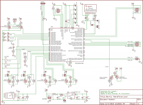
Rev4.1 Schematic (click for full size)
At this point I do have navigation software that (in theory anyway) steers the rocket’s parachute to return back to the launch pad. It seemed to work the one time I’ve had a chance to try it (November 6 – you can read the details in my flight test notes here). It still needs a good deal of tweaking before it’ll be working as well as I want it to – that’s a project for next year’s flying season. One day I’ll get around to posting a full update on the project here.

The code I’m posting today, like the earlier “Rev3” code, does not include the navigation code. But it does include everything else – logging altimeter, parachute deployment, GPS, servo control, etc. Because of the “abuse potential” of the nav code (think of navigating things to places where they ought not to be), I don’t intend to make the nav source code public. Once it’s working well, I might be interested in working with reputable vendors to sell hardware that includes this function, but if I do, it’ll have some protections in place against abuse. The main protection I’m considering is to limit the target location the system will aim for – it has to be a place the unit has physically been since it was powered up (you won’t be able to program in some other location). That way, if you’re not allowed to go somewhere with a handful of blinking rocket electronics, you can’t land the rocket there either. I’d like feedback on this idea. (Yes, anything can be hacked if you put enough effort into it, but my goal is to make it harder to hack the system than for “bad guys” to build their own – there are, after all, books on the subject…)

Anyway, here are the links to the hardware design (schematics only) and software. The deal on rights is exactly the same as with the “Rev3” postings:

Hardware rights: I hereby grant everyone and everything in the universe permission to use and modify this hardware design for any purpose whatsoever. In exchange, you agree not to sue me about it. I make no promises. By using the design you agree that if you’re unhappy the most I owe you is what you paid me (zip). That seems fair.

Here is the schematic for the hardware, in both PDF and as the original CadSoft EAGLE file (see also the ReadMe.txt in there): Rev4.1Schematic.zip

And for the software:

Software rights: I hereby grant everyone and everything in the universe permission to use and modify this software for any NON-COMMERCIAL purpose whatsoever, PROVIDED that you (a) agree not to sue me about it, (b) credit Nerdfever.com as the original source of the software in any publications, and (c) agree that I make no promises and that if you’re unhappy the most I owe you is what you paid me (zip, zero, nada, nothing). Oh, and you agree to USE THIS AT YOUR OWN RISK, that you’re a responsible adult and know that rockets can be dangerous and hurt people if you’re not careful (regardless of whether or not software is involved) so you’ll be careful and will not blame anyone else if you screw up (especially me).

I’ll be very pleased if you leave a comment or drop me an email if you find it useful, but you don’t have to.

For COMMERCIAL use, ask my permission first. If you’re going to make lots of money off my work, I’d like a (oh-so small and reasonable) cut. But I’ve no intention of giving anybody heartache over small amounts – just ask, I think you’ll find me surprisingly easy to deal with.

Here is the the Rev4 code for PIC32, including the Microchip MPLAB IDE project files, just as it appears in the project folder: Rev4.1Code.zip

Although it’s improved in lots of minor ways, the structure of the code is very similar to the Rev3 code, so please use the 6-part posting from last year as a guide to the software. The main UI change from then is that arming/disarming is now done via a reed switch. This lets me arm and disarm the system on the launch pad using a magnet, so I don’t have to make holes in the rocket body for a switch (and worry about lining up the switch with the hole). (Search for “MAGNET” in the code).

Feedback and suggestions for improvement are very welcome. I’m very happy to help out anyone who wants to work with this stuff – just drop me an email or post a comment here.

Video editing for scientific analysis

Or, Sony Vegas 101

Over the last few weeks a lot of my spare time has been going into learning how to edit videos – mostly of rocket launches and tests. Video is a great medium for capturing and carefully reviewing fast-moving objects – a standard (NTSC) camcorder captures 60 fields (half-frames, sort of) each second, which gives you a lot of time resolution to see what is going on.

For the last dozen years or so, ever since video editing became reasonably practical on a PC, I’ve periodically attempted to learn how to edit video, but it always seemed impossibly complex. This was despite the fact that I have a pretty good technical background in video – I sat on the the committee that developed the H.264 standard. (Hi Gary, Hi Thomas. I don’t miss your meetings at all.)

But I’ve finally managed it, and it turned out to be much less bad than it seemed (as usual). I’ll try to pass along the key tricks to getting it working.

Caveat: My focus has been on editing digital video from a consumer-type HD camcorder (a Canon HF100), for ultimate viewing on a computer (a Windows box). So I’m assuming you have already copied the .MTS files of your video clips from the SD card and have them to start with.

I’ll start with the Executive Summary (applicable to rocketry-type videos), then explain:

  • Camcorder setup (Canon HF100 or similar):
    • Use a gun sight as a viewfinder
    • Shortest possible shutter speed (1/2000 second is good)
    • Manually focus at infinity (turn off autofocus)
    • Turn on image stabilization
    • Set highest possible bit rate
    • Record at 60i
    • Get far away (> 100′)
  • Video editing – use Sony Vegas
    • Project settings
      • 1920×1080
      • 59.94 frames/second
      • Progressive scan
      • Deinterlace by interpolation
      • 32-bit floating point (video levels)
      • UNCHECK “Adjust source media”
    • Preview rendering quality: Set to Good (auto) or Best
      • Anything less than Good won’t de-interlace (on preview)
    • Add Sony Color Corrector
      • Gain = ((17+255)/255) = 1.06666667
      • Offset = -17
    • Options>GridSpacing>Frames
    • Options>Quantize to Frames
    • Output: Render As…
      • Audio: Default stereo at 44.1 kHz
      • MainConcepts AVCHD (H.264):
        • 1920×1080 (do not resample)
        • Progressive scan
        • Best
        • Main profile
        • 2-pass VBR (for quality)
        • Use CPU only (only if you get errors with the GPU)
  • 4 Mbps minimum; 10 to 14 Mbps is better

ABOUT VIDEO

Just like Thomas Edison’s motion picture film, video is a series of still pictures that are captured and shown in quick succession, to create the illusion of smooth motion. When you’re going to carefully analyze an event after the fact, it can be really helpful to look at those still pictures one at a time, or in slow-motion. You can easily measure the duration and timing of events by counting frames (pictures), because the frames are taken at fixed intervals of time.

In NTSC countries (USA, Canada, Japan), the standard video format is 30 frames (pictures)/second, in the rest of the world it’s 25 frames/second (PAL and SECAM standards). Since I’m in the USA I’m going to use the 30 frames/second number (adjust accordingly if that doesn’t fit where you live).

So, for example, if frame 30 shows an event starting, and frame 36 shows it ending, you know the event was 6 frame intervals long. That’s 6/30ths of a second (0.2 seconds).

Only…it’s not really 30 frames/second, it’s actually (30 * 1000/1001) frames/second, which is a tiny bit more than 29.97 frames/second. The reason for that is related to the transition from black-and-white to color broadcasting in the 1950s, the details of which are irrelevant today. Just accept it – when people say “30 Hz” in video, they mean 30 * 1000/1001  Hz. (They also mean that if they say “29.97 Hz”, which is a lot closer to the exact value, but not quite there.)

Sometimes you’ll hear about “progressive” video, often abbreviated to “p” as in “720p” and “1080p”. Progressive video is what you’d expect video to be – a simple series of still pictures captured and shown one after another, like frames of a movie film.

Other times you’ll hear about “interlaced” video (as in “1080i”). That…I’ll get to.

VIDEO CAPTURE WITH THE CAMCORDER

I’ve been using a Canon HF100 consumer-level HD camcorder. It’s pretty good. My only complaints are that it has a mild rolling shutter problem (not nearly as bad as my DSLR’s video mode), and a clunky UI for manual control. The newer models are probably better.

Viewfinder – use a gun sight

The biggest problem I’ve had with it is tracking fast-moving rockets with the non-existent viewfinder. I don’t count the LCD screen as a viewfinder – because it’s 4 inches from your nose, your eyes can’t focus on the screen and the distant rocket at the same time. And if you look at the LCD screen, then the moment the rocket (or whatever) goes off the screen, you have no idea what direction to go to find it. This is a serious problem when you’re zoomed in a long way, as your field of view is small.

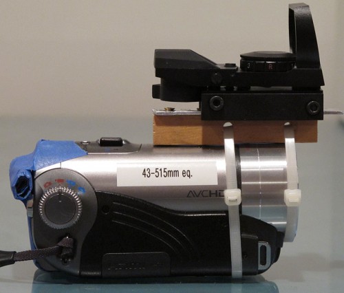
After trying several alternatives (“sports finders”, cardboard tubes, optics), the best solution was to attach a gun sight to the camcorder. It has no magnification, just projects a target into your field of view. It has little set-screws for adjusting it, so you tweak these until the target points at the exact middle of the picture when the camera is zoomed in all the way. That way, as long as you keep the target on what you’re trying to shoot, it’ll be in the picture. The one I used cost about $45; I attached it with cable ties, a block of wood, some Blu-tack (under the wood), and a strip of scrap metal.

Canon HF100 camcorder with gun sight viewfinder. The masking tape is to prevent my face from hitting the “record” button.

Setting up the camcorder

The camcorder has dozens of things you can set. These are the ones that matter for videos of fast-moving things like rockets:

Shutter speed – set to 1/2000 second (or whatever is the fastest it’ll go)

The less time the shutter is open, the less motion blur you’ll get in each picture. As long as you’re shooting in daylight, there will still be enough light – the camera will open up the aperture and/or crank up the gain to compensate. Don’t set the shutter to “auto”; it’ll be much too slow to freeze fast motion and you’ll get blur. (“Auto” is fine for videos of your kids.)

Use manual focus
Continue reading

How to descale a Bosch Tassimo coffee machine


This is another post tagged “sad”.

Does your circa 2009 Bosch Tassimo coffee machine have the red descaling light on? And the red light won’t turn off, even tho you followed the descaling instructions in the manual? (It should look like this:)

The problem is the manual is wrong. I don’t know how they managed it, but it’s plain wrong.

Here’s what to do:

  1. Take out the water filter from the water tank (if you have one). Descaling won’t work with the filter in there.
  2. Mix up 500 mL of descaling solution in the water supply bucket. You must have at least 500 mL of solution in there or it will run out and you’ll have to start over.
  3. Put the cleaning disc into the machine and close the little disc door.
  4. Put a cup that will hold at least 500 mL into the machine (you will probably want to take out the cup stand to make room for it). If the cup won’t hold 500 mL, it’ll overflow and you’ll have a mess.
  5. This is the key: press and hold the brew button for at least 3 seconds. Now wait 20 minutes.

After 3 seconds the green and red lights will start flashing simultaneously – that indicates you’ve started the descaling cycle, which will run 500 mL of the solution thru the machine and into the cup. It goes slowly, in small bursts over about 20 minutes. When it’s done, the red light will go out. Then flush out the machine by running lots of clean water thru it (per the manual), and put back the water filter (if you want, and if your model has one).

If you stop the machine before it’s done with the full cycle, you’ll have to start over.

This procedure is hinted at in icon-speak (no words) on the little booklet that the cleaning disc comes in. It’s totally different from what the manual says, with the key difference that this procedure works.

Enjoy your coffee.


Is MS Word 2003 loading slower and slower?

It was for me. Turned out that that my Normal.dot file, usually 38 kBytes, had grown to 1.4 MBytes. That’s what was taking so long – loading it each time.

Simply deleting the file was a good temporary fix back in May (Word automatically re-creates it if it’s missing). On Win7 for me it was in:

C:\Users\Dave\AppData\Roaming\Microsoft\Templates

Lately, it’s been happening again – this time Normal.dot had grown to 1.8 MBytes (since May!).

Investigation revealed that the file grew by about 2 kBytes each time I loaded a file. I had a look at the binary of Normal.dot to see what was taking up so much space, and saw lots of Unicode text reading things like “Sign in to Office Live Workspace beta”.

So I un-installed “Microsoft Office Live Add-in”. Now Normal.dot doesn’t grow anymore.

This post is tagged “Sad”.

New “Rev 4” hardware based on the PIC32

This project was mentioned in this month’s Sport Rocketry magazine, so I thought it would be a good time to post a status update on the project.

(If this is your first visit here, have a look here for background as to what the project is about.)

REV4 PCB

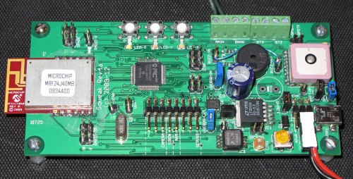
This spring I finished my “Rev4” circuit board, with the PIC32 CPU:

This board also has a USB interface and a Microchip MiWi (ZigBee/IEEE 802.15.4) radio module on board. The “Rev4A” board pictured here is using the GlobalTop FGPMMOPA6 GPS module (the big square thing on the right), which reports at 200 mS intervals. I’ve bought a few of the new PA6B modules (100 mS), but haven’t tried them yet.

The only problem I discovered with the Rev4a hardware was my circuit for driving the piezo buzzer – what I’d meant as an amplifier to make it louder instead shorted it. Happily I’d left enough test jumpers that bypassing the amplifier circuit was nothing more than leaving out 2 berg jumpers and adding a single wire between the pins. So it works and makes noise, but isn’t as loud as I’d like.

I’ve since designed and had fabricated (BatchPCB again) a “Rev4b” PCB that fixes this problem and is about 30% smaller, but I haven’t yet had time to populate and test it.

SOFTWARE

I started by porting over all my old 8-bit (PIC18) code to the PIC32, making improvements along the way. So far I haven’t written any code to drive the radio or the USB port – the hardware is all there, but it doesn’t do anything yet.

I test-flew this board twice on April 24 at the CMASS launch in Amesbury MA. Neither flight was perfect (see Flight Test Notes for flights # 26 and 27) but both were sucessful enough to build some confidence in the stability of the Rev4 hardware and software.

The next project was to either get the telemetry radio and USB working, or to port the navigation code (that will steer the rocket back to the launch site using GPS information) onto the Rev4 hardware.

I tend to like to do things slowly and carefully, one step at a time (perfectionism), so my inclination was to get all the Rev4 hardware working before I started on the final goal of navigation. But the famous words of Michael Faraday when young William Crookes asked him the secret of his scientific success came to mind:

The secret is comprised in three words — Work, finish, publish.

It had been 4 full years since I’d started this project, and I still wasn’t navigating back to the launch site. While it’s true that this is only a hobby project, and I’d been busy in the same period starting a business, raising a family, etc., nonetheless I decided it was time to focus on finishing first, and polishing later.

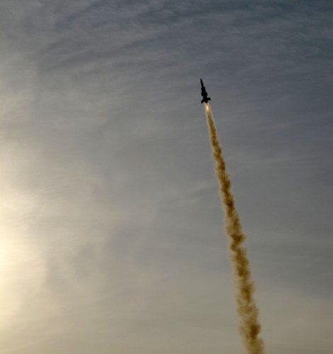
I’ll bring things up-to-date on that in my next posting. For now I’ll leave you with a video of my most recent flight, from yesterday, July 17:


Don’t buy a lithium battery charger

This post will introduce you to battery charging and tell you how to charge lithium cells using a bench power supply.

Executive summary:

Attach a single lithium cell to the power supply and set it at 4.20 volts and 0.5C. Leave it charging until the current drops to 1/20C. Repeat for all cells in the pack.

I use lithium cells (LiPo, LiIon, etc.) in a lot of my projects – usually surplus cellphone batteries. They have much better energy/volume and energy/weight ratios than other battery types (the next best is NiMH).

But they have a reputation of being “tricky” to charge, and needing a special charger.

Not really.

Put your money into a bench power supply instead of a lithium charger. The power supply will do the charging just as well, and is tremendously useful for other things as well.

You need a constant voltage/constant current (CV/CC) DC power supply. This lets you set a maximum voltage and a maximum current at the same time.

The Mastech 3003D is typical of inexpensive CV/CC bench power supplies. It goes for $110 to $150 online, and is well worth the money. (Mastech is Chinese, but the quality seems OK. Other brands are fine too.)

Batteries 101

Batteries are made up of cells in series. Each cell has a typical voltage that depends on its chemistry – carbon-zinc and alkaline cells are around 1.5 volts, NiCd and NiMH around 1.2 volts, lithium cells around 3.3 to 3.7 volts. Lead-acid cells are around 2 volts.

To get higher voltages, cells are put in series in a battery. Sometimes there’s only one cell in the battery, as with typical lithium “batteries” at 3.6v or so. (Technically these ought to be called just “cells” not “batteries” since there’s only one cell, but people often call them batteries anyway.)

A cell (or battery) has a capacity rated in amp-hours (AH or mAH). For example, an 800 mAH battery can produce 800 mA for 1 hour, or 400 mA for 2 hours, or 8 mA for 100 hours (at the rated voltage) before the battery is drained. In theory.

In practice, cells are usually rated assuming you’ll be draining them over 20 hours. Most batteries produce more energy if you drain them slowly. So, a 5 AH battery can produce something like 250 mA for 20 hours (0.25 * 20 = 5). If you drained it at a rate of 5 amps, it would die before one hour is up.

Also, the voltage gradually drops as you discharge the battery – it starts a little above the rated voltage, then spends most of the time near the rated voltage. When it starts to drop quickly from there, it’s empty.

The current needed to (theoretically) empty the battery in 1 hour is called C.  Charge and discharge currents are given in units of C. For a 800 mAH cellphone battery, C is 800 mA.

Most cells have a maximum discharge current beyond which their performance drops off dramatically. For tiny watch batteries (coin cells), this current is really small – something like 0.002C. (“0.002C” would often be called the “500-hour rate”.) These cells are designed to run a long time at tiny currents. At the opposite extreme are lithium polymer cells designed for high-current uses such as in electric-powered model airplanes. I’ve seen some with a maximum discharge rate of 20C – meaning you can drain them in 1/20 of an hour (3 minutes) reasonably efficiently and without damaging them!

Charging

Most rechargeable battery types can be charged at modest constant currents, without worrying about voltage – something like 0.05 to 0.1C (NiMH, NiCd, lead-acid). So you could charge one of these cell types in 10 or 20 hours with your bench power supply by setting the current to 0.1C or so (500 mA for a 5 AH battery), and just turning the voltage up all the way (so it’s not limited).

(I’m not talking fast charge here – that’s a whole other topic; ask Google about that, not me).

Lithium cells are different. They need to be charged at a constant current until reaching a specific voltage, and then constant voltage. But that’s trivial if you have a CV/CC bench power supply. Continue reading

FileTimes – Discover your own work patterns

FileTimes.exe is a little program I wrote 10 years ago when I was learning C++. Download it here.

It plots a graph of the write timestamps on all the files in any folder you select (recursing thru all the subfolders). You can look at the time stamps by time of day, week, month or year. You can also control the averaging period with a slider.

Plotted by time of day

It’s fun for looking at when you’re busy – for example you can see here that I’m definitely not a morning person – I don’t really get going much before 10am.

If you move the mouse over the graph, it shows how many files were modified at the time point the mouse is at.

It works on any version of Windows since Win95 (up to Win7, so far). There’s no installer, just run the .EXE wherever you put it (the desktop is fine). It doesn’t mess with the registry, won’t modify your files at all, won’t create any files anywhere, and doesn’t have any viruses or spyware – I promise.

I don't slack off much on weekends, it seems.

It’s free – I hereby put it in the public domain.

This version says “ALPHA TEST VERSION – DO NOT DISTRIBUTE”, but it’s 10 years old. I haven’t Continue reading

Idea: Intelligent heating tape/sleeve

Edit 2014-11: Nevermind.

Another idea I don’t want to bother thinking about patenting-

How about an intelligent heating tape/sleeve that can be used to keep something (for example, water pipes) permanently above some pre-set temperature?

I imagine a sleeve (possibly surrounded by insulation) that can be put around a water pipe, that contains:

  • A resistive heater
  • A temperature sensor
  • A FET to turn the heater on when the temp falls below the set value (a thermostat)

This would be great to prevent pipes from freezing in the winter in unused rooms (with minimum expenditure of energy). Of course, one can imagine lots of other uses.

I’d power the thing from 12v or so, so nobody gets electrocuted if they cut into it, and to simplify conformance with building codes. You’d probably want the power supply to have a battery backup so it’ll keep working if the power goes out for a while.

If it’s used on a copper pipe, the pipe itself could form the return path, leaving only a single wire to power the thing.

It would have to be segmented so that the stuff can be cut or torn to the desired length. Each segment should have its own thermostat so only the part that needs heat consumes power. And it should be removable without too much trouble, to allow for repair access to the pipe.

Does this thing already exist? Anybody know? (Bill, you reading this?)