DIY conformal coating

I’ve been having some problems with nasty black somewhat conductive sooty stuff getting onto my PCBs. I decided the quickest solution was conformal coating to protect the PCB.

But I’ve never done that before and don’t know how. At first I thought of painting on epoxy with a paintbrush. But I was worried that once I coat the board it’ll be difficult to work on if I need to replace a component or something.

So I decided to try it with hot glue. Hot glue is removable, and unlike epoxy, isn’t brittle. And if I get some on the wrong place (like a connector pin or PCB button), I can take it off again.

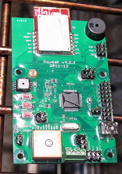
Board fresh out of oven

I don’t really know if this is a good idea or not, but I tried it and it seems pretty OK so far.

First, I cleaned the sooty stuff off the PCB the best I could with 100% ethanol and a toothbrush. Then I baked it dry in a convection oven at 210 F for 30 minutes. It still worked.

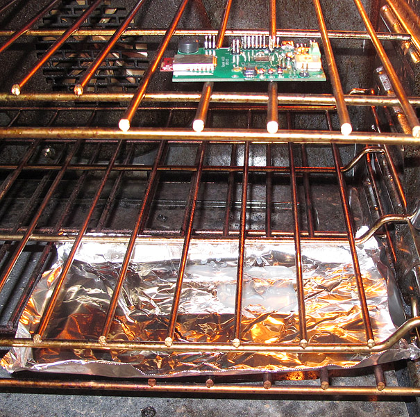
Board in oven, above aluminum foil drip tray

Then I covered all the parts and traces with hot glue with an industrial-type glue gun (a hobby type gun would probably work too, but that’s what I have). I used Bostik type 0130 glue, which I think is pretty much the standard stuff you get in a hardware store.

I did my best to avoid covering connector pins and moving parts (buttons, piezo sounder, etc.).

The result was really ugly. Since the oven had worked well for drying the board, I thought I’d try to reflow the glue in the oven to let excess glue drip off and even out the glue.

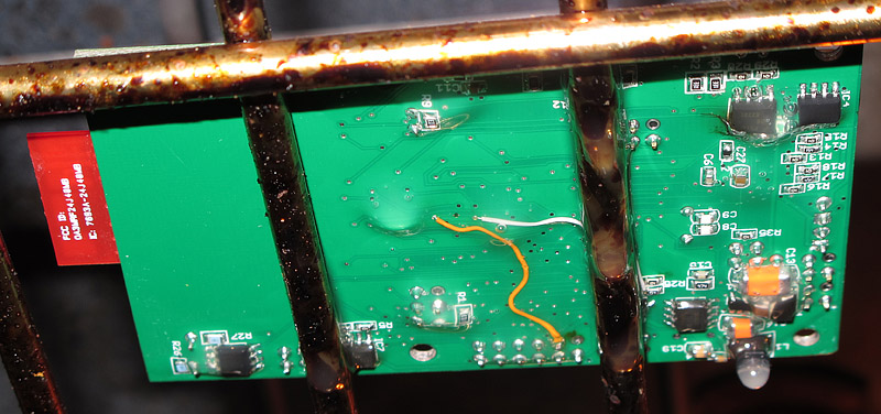
It seemed to work pretty well. After experimenting with temperature a little, I decided 260 F for half an hour was about right. I made a drip catcher out of aluminum foil and put that under the board.

Bottom of board after reflow in oven. Note the drips.

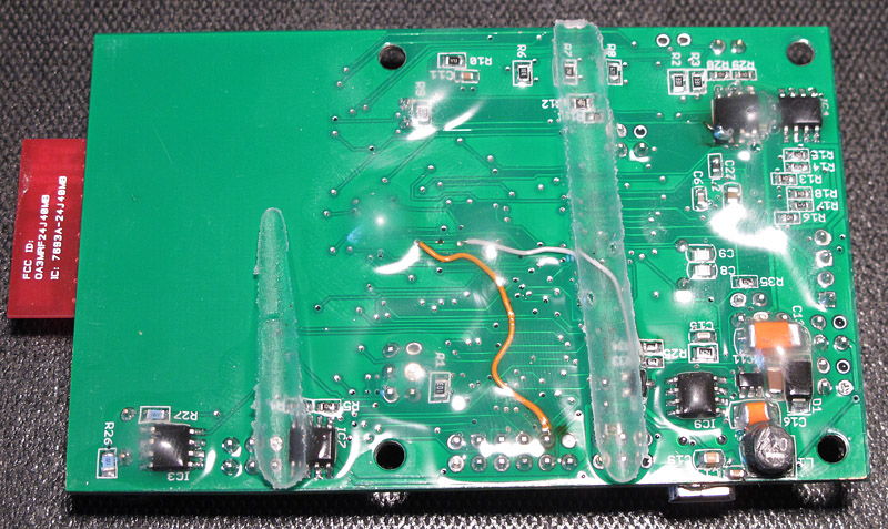
Once it cooled off, it was really difficult to get the board off the oven rack (that glue works well).

And I still haven’t found a great way to clean the dripped glue off the oven racks. The best I could do was reheat the oven to about 300 F and then wipe off the glue with paper towels while it’s hot (carefully!). (My wife never reads my blog postings anyway…)

Next time I think I’ll remove all but one oven rack first, and hang the board from that rack so no glue gets on the rack.

Bottom of board after unsticking it from the oven rack

Notes on using Eagle PCB

These (link to PDF file) [updated 2012-06] are my notes for using Eagle PCB, an excellent CAD program for printed circuit board design with a free (but still fully functional) “light” version.  Most of the text is my own, but there are places where I’ve cut-and-pasted information from the Eagle documentation or material found online.

To go with the notes, here is a .ZIP file containing my customized EAGLE.SCR file (sets defaults on starting Eagle), default.dru (defaults for routing), and Dave-gerb274x(2layer).cam (for making gerber files; works fine with BatchPCB).

The notes are not meant as a replacement for the Eagle documentation, but rather as commentary and interpretation.

I’ve been using BatchPCB.com to manufacture boards; their design rules influence some of the notes.

I find Eagle’s user interface counter-intuitive in many ways.  It’s powerful, but the assumptions differ a lot from common GUI programs like MS Office and Photoshop.  The fact that the manual is a poor translation from German doesn’t help. So I have to refer to these notes to refresh my memory about how Eagle works after not using it for a while.

I make no promises that this material is accurate; I write what I learn but sometimes I may misunderstand.  Feedback with corrections and improvements are welcome; please post them on NerdFever.com or email to dave@nerdfever.REMOVE_THIS.com.

Driving the “808” keychain camera with a microcontroller

I’ve been playing around with the “808” keychain video camera. This is a tiny digital video recorder that captures very good quality video, yet sells for less than $15, shipped! (Try eBay.) That includes an internal LiIon battery, recharged via the USB port, but not the microSD card you need to buy separately. (My hat is off to the Chinese manufacturers – how they can do it at that price I don’t know.)

Quite a few of the flyers in the local CMASS rocket club have been attaching these to model rockets (using high-tech attachment methods like masking tape or velcro) to get in-flight videos.

Chuck Lohr’s wonderful site at http://www.chucklohr.com/808/ is the place for technical information on this thing – this posting is my little contribution to the cause.
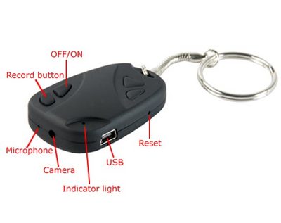
The “808” keychain camera
(image courtesy of http://squeezebuck.blogspot.com/2011/02/cheap-keychain-spy-dvr-camera-808-8.html)

I’ve been working on installing mine (a so-called #3 type – see Chuck Lohr’s page) in the electronics bay of my GPS-steered rocket recovery system, to take videos of the parachute deploying and being steered in flight (plus, it’s cool).

Since a high-power rocket will sometimes sit on the launch pad for 30-60 minutes before flight, I need a way to turn it on with my on-board microcontroller at launch time.

This technique should work with any microcontroller that runs on 3.3 volts (the same voltage as the logic in the camera). The specifics apply to the #3 type camera, but the general idea will probably work with the others as well.

If you open up the #3 (carefully, avoid stripping or cracking the delicate plastic screw holes), the side of the board with the buttons looks like this:
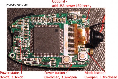
“808” keychain camera, type “#3”, button side
(click image for larger version)

I’ve marked four positions on the board, you want to solder wires onto these:

  • The right side of the capacitor near the left end of the board. This can be used to monitor whether the camera is turned on. When there is 3.3v on this cap, the camera is turned on. When there’s 0v (ground), it’s off. Connect this to an input line on your microcontroller.
  • The lower right connection on the power button. This controls when the power button is pressed; connect it to an output. Driving this pad low (0v) presses the power button, driving it to 3.3v releases it.
  • The upper right connection on the mode button. This controls when the mode button is pressed. The voltages on it are the opposite of the power button: 3.3v presses the button, 0v releases it.
  • Note there’s a place at the top right of the board for another SMD LED. I soldered a green one there to see what it would do – it lights up when the board is connected to a live USB port.
  • Last, you’ll need a ground connection. I found the best place to be any one of the four tabs that attach the USB connector (on the other side of the board, not shown). Just add a blob of solder and attach the ground wire.

[Update 2011-07: Since I wrote this posting, I got a 2nd “#3” camera on eBay. This one appears identical externally and functionally, but internally has a newer PCB. Driving it is identical, except that the mode button has opposite polarity – 0v is closed, 3.3v is open. YMMV.]

Once you’ve got at least the 3 minimum wires connected up (power button, mode button, and ground), operating the camera is a simple matter of software.

To take a movie on the #3 camera (others may vary), press the power button for 1.3 seconds to turn on the camera. Then release it and wait 4.5 seconds. Then press the mode button for 3.0 seconds. The camera will start recording a movie.

To stop it, just turn off the camera by pressing the power button for 1.3 seconds again. [Update 2011-07: A better way is to press the mode button for 200 mS.]

These times are the minimum values I found would work reliably. Note that if you wait more than about 40 seconds between pressing the power button and the mode button, the camera will turn itself off, and you’ll have to start over.

Here’s my modified 808, ready to connect up to the microcontroller – I can still press the buttons with a little screwdriver.
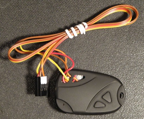
Modified 808 camera, all buttoned up.


Update, September 2013:

Lately I’ve had a few people ask me for the source code I use to drive the camera, so here it is: videoCam.zip.

It’s pretty self-explanatory, but the idea is that you call InitVideo() once to initialize it, then call ManageVideo() periodically (at least every 100 mS or so) to manage the camera. The global “Video” tells it if you want to be recording or not.

It’s implemented as a simple finite-state machine.

Post any questions here; I’ll try to answer.

“Rev4” PCB and software

[Update October 2011: This post is no longer the latest version version of the board; see here.]

Almost a year ago I posted the schematics and software for the “Rev3” version of my rocket flight computer/altimeter.

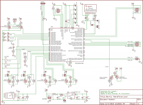
I’ve now got the code ported over and working well on the “Rev4” hardware. This is far more integrated – the parachute deployment circuits, piezo speaker, and GPS are all on the PCB now, and it’s based on the much more powerful PIC32 MCU. So (per a couple of requests), I’m posting the software and schematics for that today.

Rev4.1 Schematic (click for full size)
At this point I do have navigation software that (in theory anyway) steers the rocket’s parachute to return back to the launch pad. It seemed to work the one time I’ve had a chance to try it (November 6 – you can read the details in my flight test notes here). It still needs a good deal of tweaking before it’ll be working as well as I want it to – that’s a project for next year’s flying season. One day I’ll get around to posting a full update on the project here.

The code I’m posting today, like the earlier “Rev3” code, does not include the navigation code. But it does include everything else – logging altimeter, parachute deployment, GPS, servo control, etc. Because of the “abuse potential” of the nav code (think of navigating things to places where they ought not to be), I don’t intend to make the nav source code public. Once it’s working well, I might be interested in working with reputable vendors to sell hardware that includes this function, but if I do, it’ll have some protections in place against abuse. The main protection I’m considering is to limit the target location the system will aim for – it has to be a place the unit has physically been since it was powered up (you won’t be able to program in some other location). That way, if you’re not allowed to go somewhere with a handful of blinking rocket electronics, you can’t land the rocket there either. I’d like feedback on this idea. (Yes, anything can be hacked if you put enough effort into it, but my goal is to make it harder to hack the system than for “bad guys” to build their own – there are, after all, books on the subject…)

Anyway, here are the links to the hardware design (schematics only) and software. The deal on rights is exactly the same as with the “Rev3” postings:

Hardware rights: I hereby grant everyone and everything in the universe permission to use and modify this hardware design for any purpose whatsoever. In exchange, you agree not to sue me about it. I make no promises. By using the design you agree that if you’re unhappy the most I owe you is what you paid me (zip). That seems fair.

Here is the schematic for the hardware, in both PDF and as the original CadSoft EAGLE file (see also the ReadMe.txt in there): Rev4.1Schematic.zip

And for the software:

Software rights: I hereby grant everyone and everything in the universe permission to use and modify this software for any NON-COMMERCIAL purpose whatsoever, PROVIDED that you (a) agree not to sue me about it, (b) credit Nerdfever.com as the original source of the software in any publications, and (c) agree that I make no promises and that if you’re unhappy the most I owe you is what you paid me (zip, zero, nada, nothing). Oh, and you agree to USE THIS AT YOUR OWN RISK, that you’re a responsible adult and know that rockets can be dangerous and hurt people if you’re not careful (regardless of whether or not software is involved) so you’ll be careful and will not blame anyone else if you screw up (especially me).

I’ll be very pleased if you leave a comment or drop me an email if you find it useful, but you don’t have to.

For COMMERCIAL use, ask my permission first. If you’re going to make lots of money off my work, I’d like a (oh-so small and reasonable) cut. But I’ve no intention of giving anybody heartache over small amounts – just ask, I think you’ll find me surprisingly easy to deal with.

Here is the the Rev4 code for PIC32, including the Microchip MPLAB IDE project files, just as it appears in the project folder: Rev4.1Code.zip

Although it’s improved in lots of minor ways, the structure of the code is very similar to the Rev3 code, so please use the 6-part posting from last year as a guide to the software. The main UI change from then is that arming/disarming is now done via a reed switch. This lets me arm and disarm the system on the launch pad using a magnet, so I don’t have to make holes in the rocket body for a switch (and worry about lining up the switch with the hole). (Search for “MAGNET” in the code).

Feedback and suggestions for improvement are very welcome. I’m very happy to help out anyone who wants to work with this stuff – just drop me an email or post a comment here.

New, improved SMD Pitch-o-meter

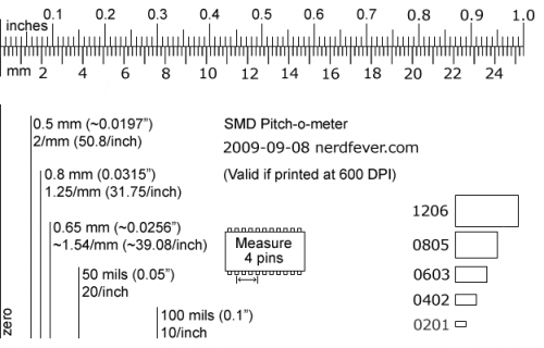
Here’s a new, improved SMD Pitch-o-meter for all your SMD measurement needs.  (Also may be useful as a general microscopy scale.)

This version has a more readable distance scale marked in increments of 0.01 inches (10 mil) and 0.1 millimeters (100 microns), plus size outlines for 1206, 0805, 0603, 0402, and 0201 SMD packages.

Print it out at 600 pixels/inch (glossy photo paper recommended) and keep it handy near your binocular microscope.

Be sure to click on the image and download the full-sized version.

SMD Pitch-o-meter

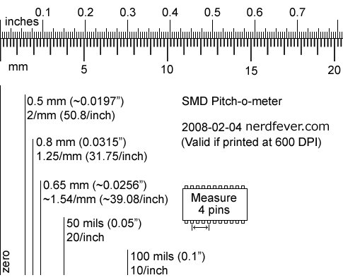
SMD Pitch-o-meter

To measure SMD lead pitch (usually called parameter ‘e’ on datasheets) measure 4 (four) pins on the part from the line marked “zero”. Then read up for the pitch.

SMD Pitch-o-meter

If you’re working with SMD stuff, it’s really helpful to have a 10 to 20 power stereo microscope (stereo, not “binocular” – it’s not the same thing) to see what you’re doing.

(The most common type is called a “dissection microscope” – try eBay; they can be had for < US$100.) Here's something I made to help measure and identify SMD parts under the microscope - the SMD Pitch-o-meter: [Update: See the new, improved version here.]

Print it out at 600 DPI (most any Canon or HP printer – I don’t know what will happen with an Epson printer – they do 720 DPI. It might scale it OK, might not.).

It has a scale of inches (to 1/250″) and millimeters (to 0.2mm) for measuring parts.

To measure SMD lead pitch (usually called parameter ‘e’ on datasheets) measure 4 (four) pins on the part from the line marked “zero”. Then read up for the pitch.