Hewlett Packard > Agilent > Keysight … WTF?

What a way to ruin a great brand. For no apparent reason at all.

They could have called it “Pewlett Hackard”. Heck, they could have called it “Tektronix”. (Those guys in Beaverton seem to have no use for that name anymore.)

The monkeys are running the henhouse. (Or, um, something like that.)


Oh, and…get off my lawn!

Saleae Logic Analyzer

I’ve had this thing in my drawer for 2 years; just got to use it for the first time yesterday.

It’s fantastic – really worth $150.

Saleae Logic Analyzer

Saleae Logic Analyzer

Now they have new versions that do analog, too (low-bandwidth, tho).

The nice thing about the Saleae thing is the software – it’s really amazingly simple and effective (you can download a demo from their website without the hardware).

I’ve used other logic analyzers – this is miles ahead. (Also way, way, better than the protocol decode on my new Rigol DS2072A DSO.)

https://www.saleae.com/logic

[No, they didn’t pay me anything to write this.]

Directions

My 11-year-old son asked me last night if there was an East Pole or West Pole.

I told him he should be able to figure that out for himself; I asked him the leading question “what is the definition of East?”.

It didn’t go well. Then he asked if it would be different on Mars if Mars was “upside down” compared to the Earth. That didn’t go well either – severe conflict of mental models.

They don’t teach geography (or in this case perhaps astronomy) very clearly in school.

But then dictionaries have huge trouble with this, too.

Here are my definitions:

East: The direction in which the Earth (or any planet) spins.

West: The direction opposite to East.

North: The direction 90 degrees to the left of East.

South: The direction 90 degrees to the right of East.

Compare that with any dictionary you like.


Numpy == goodness! (deinterlacing video in Numpy)

A few posts back I was trying to get Linux to record and play video at the same time.

I gave up on that, but got it working under Windows with Python; I’ll post the source for that here at some point.

A big part of the solution was OpenCV, PyGame and Numpy.

I’m hardly the first to say it, but I’m excited – Numpy is goodness!

My (stupid) video capture device grabs both interlaced fields of SDTV and composes them into a single frame. So instead of getting clean 720×240 at 60 Hz (sampling every other line, interlaced), you get 720×480 at 30 Hz with horrible herringbone interlace artifacts if there is any movement in the scene.

The artifacts were really annoying, so I found a way to get Numpy to copy all the even numbered lines on top of the odd numbered lines to get rid of the interlace artifacts:

img[1::2] = img[::2]

That’s it – one line of code. And it’s fast (machine speed)! My laptop does it easily in real time. And I learned enough to do it after just 20 minutes reading the Numpy tutorial.

Then, I decided I could do better – instead of just doubling the even lines, I could interpolate between them to produce the odd-numbered lines as the average of the even-numbered lines (above and below):

img[1:-1:2] = img[0:-2:2]/2 + img[2::2]/2

It works great! Numpy == goodness!


PS: Yes, I know I’m still throwing away half the information (the odd numbered lines); if you know a better way, please post a comment. Also, I’d like to record audio too, but OpenCV doesn’t seem to support that – if I get that working, I’ll post here.

Prime Telephoto + Tiny Sensor = Super telephoto?

Sometimes I get an idea in my head and just can’t get it out.

Modern digital cameras often have tiny sensors compared to 35mm film.

High-quality 1970s “prime” 35mm lenses had a reputation for being very sharp.

When one of those lenses is mounted on a small-sensor camera, the sensor covers only a tiny central region of the 35mm-sized image formed by the lens – essentially the sensor is cropping from the middle of the image, resulting in a telephoto effect.

This gives rise to the “crop factor” of small sensor cameras – at a given focal length, the field of view of the small sensor is much smaller (more “zoomed in”) than on the original 35mm film the lens was designed for.

What, I wondered, would images from a high-quality 1970s prime 35mm lens mounted on a modern small-sensor camera look like? Especially, could I get super-telephoto effects by mounting lenses that were considered long (telephoto) by 35mm standards, multiplied the “crop factor”?

I had to try it.

35mm film frame vs Pentax Q sensor

35mm film frame vs Pentax Q sensor

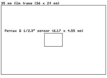
Above is a diagram showing the relative sizes of a 35mm film frame compared to the 1/2.3″ sensor in the Pentax Q.

The Q has the smallest sensor of any interchangeable lens camera I know of. While this may make it – ahem – less than ideal for general photography purposes (altho to be fair the latest versions of the Q have moved to a larger 1/1.7″ sensor, a huge improvement), that little 6.17 x 4.55 mm sensor does have an immense “crop factor” of 5.6x (comparing effective field of view at the same focal length – the number isn’t exact because the Q’s sensor has a 4:3 aspect ratio, while 35mm film is 3:2).

Off-topic, but other points in favor of the Q are the tiny flange focal distance of 9.2mm – it can mount just about any lens ever made – and Pentax’s excellent UI. I’m not sure there’s a mass market for a camera like this, but it sure can do some things that no other camera can.

So, while a “normal” 50mm lens on a 35mm camera has a 39.6 degree field of view (horizontal), the same lens on the Q sees only 7.1 degrees.

And – here’s the neat thing – a “telephoto” 200mm lens on a 35mm camera sees 10.3 degrees – but on the Q, only 1.8 degrees. That’s the equivalent of an immense 1120 mm lens in 35mm format. And a super-telephoto 500 mm lens sees just 0.71 degrees on the Q – equivalent to 2800 mm on 35mm.

So, I tried it. I got some Minolta MD/MC type prime (non-zoom) lenses on eBay, mainly because they have an excellent reputation and are a bit cheaper than other brands (because they don’t fit many modern cameras), and an adapter for the Q (also on eBay – remember I said the Q can mount almost anything?).

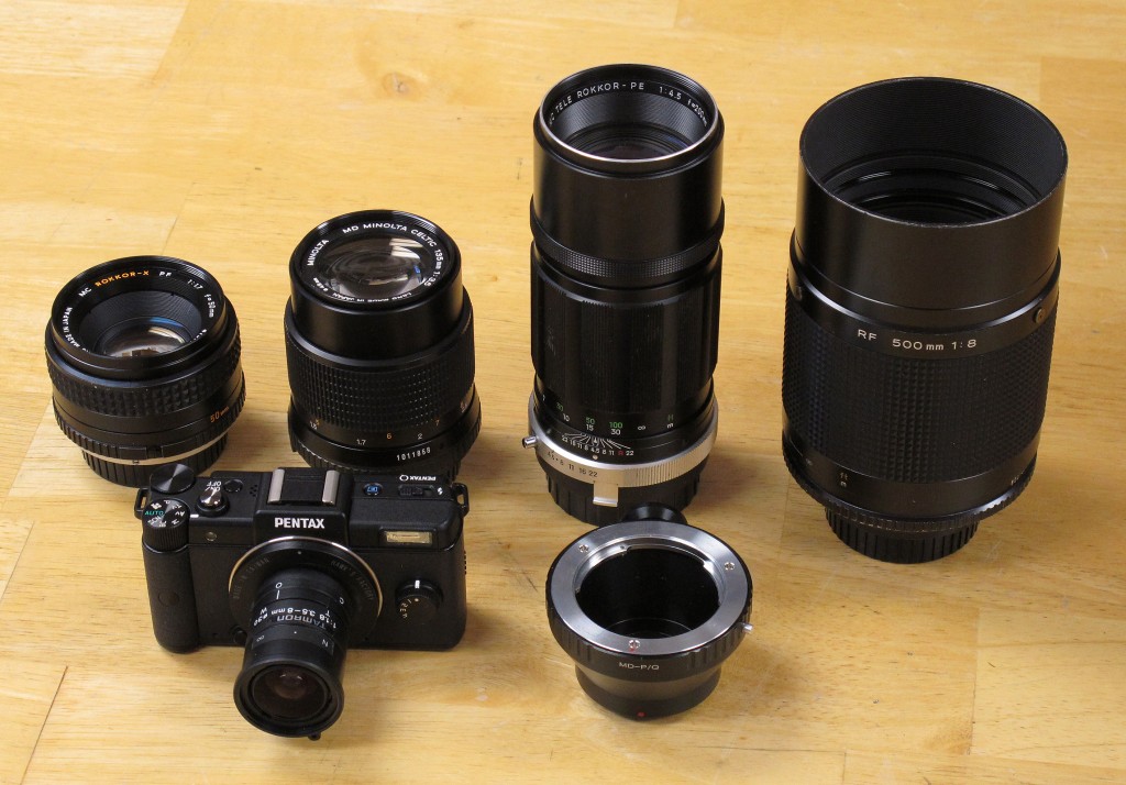
Here’s what I ended up with:

Lenses tested

Lenses tested

Left to right:

  • Minolta 50mm f/1.7 MD Rokkor-X PF
  • Minolta 135mm f/3.5 MD Celtic
  • Minolta 200mm f/4.5 MC Tele-Rokkor  PE
  • Minolta 500mm f/8 RF Rokkor-X

From what I can tell online, these are all highly-regarded lenses. The “Celtic” line was Minolta’s cheaper brand, but it seems the economy came from using cheaper materials in the mount, etc. – supposedly it is optically identical the to more expensive “Rokkor” line. And of course, these are all primes – not zooms. Even today primes are generally sharper than zooms; this was even more true in the 1970s before improved manufacturing and computerized optical design.

In the second row you see the Pentax Q with a Tamron 3.5-8mm zoom f/1.8 lens in CS mount, via a “Hawk’s Factory” CS mount adapter (I told you the Q can mount most anything…), and the Minolta MD-to-Pentax Q adapter (just a hunk of metal – no glass).
Continue reading

CreepAway

Back in 1996 I had an idea I called the “CreepAway”.

It was a device that would screen your phone calls – it would auto-answer (blocking the local ring), and then ask the caller to “Enter Extension Number” (really a password).

If the caller entered the correct password, it would ring the phone so you can answer.

If they didn’t, the caller would be sent to voicemail.

The idea is that you give both your phone number and your “extension” to your friends – they dial your number, enter your “extension”, and the phone rings.

Telemarketers and others calling at random only get to leave a voicemail.

I think this would be easy to do today with an Android app.

I’m sick and tired of getting robocalls offering me legal help with my (non-existent) IRS debt.

Somebody please build this.


Update, 2013-12:

I recently realized that not only would this be easy to do in an Android or iOS app (intercept the incoming call at the API level, assuming those APIs are exposed), but there’s an even simpler way.

Do it as a service.

Your phone company (Vonage, Google Voice, the PTT, whatever) would provide you with two numbers – a public one (to be given out) and a private one (known only to the phone company).

When people call the public number, the service provider (phone company) would prompt for the extension (or password, whatever). If the caller gives the correct one, the call is forwarded to your private number. If not, to voicemail.

That’s it. It would be trivial to implement in a modern SIP or H.323 based phone system. And they could charge for the service.

Hey – somebody – DO THIS.

What is it??

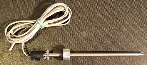
What is this?

IMG_7272_crop

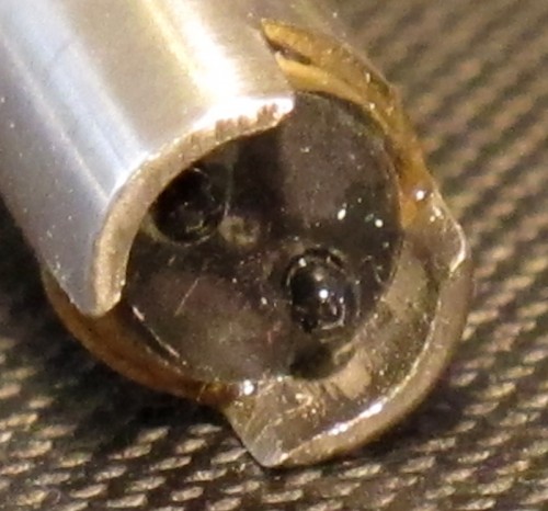
This is not a quiz or a puzzle. I want to know what it is.

All I know is that it is something used in a biology lab. This thing was found loose inside a piece of used equipment.

It’s got 4 wires coming out – looks like a standard telephone cable. When I measure, I see 2218 ohms between black and red, 2267 ohms between black and green, and 4470 ohms between red and green. Yellow seems to be disconnected (open circuit).

IMG_7273 copy

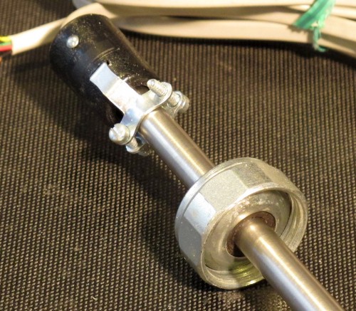
The knurled ring thing (above) tightens down a rubber stopper – looks like it was meant to go into some kind of bottle or flask. The stopper isn’t airtight tho (it’s not completely sealed against the metal tube).

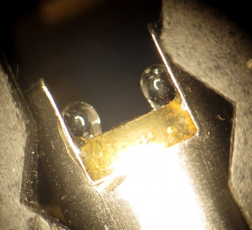
Below are oblique, end-on, and side views of the “business end”. It appears to have two little glass bulbs at the end, each with something black or dark grey inside. (The little white circles in the photos are just reflections of the ring light on my microscope.)

What is it??

IMG_7275 copy

IMG_7277 copy

IMG_7280 copy


Update, October 27 2013:

Looks like Bob was right.

When I wave a hot air gun at it (set at 100 C), the resistance between red and black instantly drops to about 1.4 k ohms, red to green goes to about 3 k ohms, and green to black goes down to 600 ohms or so. It definitely seems to be a temperature probe.

I suspect the two bulbs are arranged red – (bulb) – black – (bulb) – green, and that the two bulbs’ different responses somehow contribute to stability and/or linearization of the output. Probably it wouldn’t be too hard to calibrate it, but for now it goes on the shelf. At least I know what it’s for (even if I still don’t know who made it).

Play & record video at the same time in Linux

I didn’t think this would be so difficult.

All I want to do is play live video on my netbook (from /dev/video1:input=1:norm=NTSC) and record it at the same time. Without introducing lag.

mplayer plays the video fine (no noticeable lag).

mencoder records it fine.

The mplayer FAQ says you can do it this way:

mencoder tv:// -tv driver=v4l:width=324:height=248:outfmt=rgb24:device=/dev/video0:adevice=hw.1,0 -oac mp3lame -lameopts cbr:br=128 -flip -ovc lavc -lavcopts threads=2 -o >( tee filename.avi | mplayer -)

But that doesn’t work.

You can’t record and play at the same time because there is only one /dev/video1 device, and once either mencoder or mplayer is using it, the device is “busy” to any other program that wants to read the video stream.

I spent lots of time with mplayer, mencoder, ffmpeg, avconv, and vlc;  as far as I can tell none of them can do it, directly or indirectly. There are ways that work if you don’t mind 200 or 300 ms of extra latency over mplayer alone. But I’m doing a FPV teleoperation thing and that’s too much latency for remote control.

I found a way that sort of works. Here’s a bash script (works in Linux Mint 15, which is like Ubuntu):

#!/bin/bash
mplayer tv:// -tv device=/dev/video1:input=1:norm=NTSC -fs&
outfile=$(date +%Y-%m-%d-%H%M%S)$1.mp4
avconv -f x11grab -s 800×600 -i :0.0+112,0 -b 10M -vcodec mpeg4 $outfile

This works by running mplayer to send the live video to the screen (full screen), then running avconv at the same time to grab the video back off the display (-f x11grab) and encode it. It doesn’t add latency, but grabbing video off the display is slow – I end up with around 10 fps instead of 30.

There must be some straightforward way to “tee” /dev/video1 into two virtual devices, so both mplayer and mencoder can read them at the same time (without one of them complaining that the device is “busy”). But I haven’t found anybody who knows how. I even asked on Stack Overflow and have exactly zero responses after a day.

(If you know how, please post a comment!)


Addendum for Linux newbies (like me):

After you put the script in file “video.sh”, you have to:

chmod +x video.sh # to make it executable (just the first time), then

./video.sh # to run the script (each time you want to run it)

You’ll probably want to tweak the script, so you should know that I’m using a KWorld USB2800D USB video capture device, which puts the composite video on input=1 (the default input=0 is for S-Video) and requires you to do norm=NTSC or it’ll assume the source is PAL.

-fs makes mplayer show the video fullscreen. Since I’m doing this on my Samsung N130 netbook with a 1024×600 screen, the 4:3 video is the 800×600 pixels in the middle of the screen (starting at (1024-800)/2 = 112 pixels from the left).

Also, many thanks to Compn on the #mplayer IRC for trying really hard to help with this.


Update 2013-11-02:

I haven’t given up on this, so I’ll use this space to record progress (or non-progress).

I started a Stack Exchange thread on this.

On IRC I was told that VLC can do this. I got as far as getting it to display the video at 720×96 (yes ninety-six) resolution, with a lot of lag (the source is VGA, 640×480).  Googling about it, it seems the resolution problem is probably fixable with VLC, but the lag isn’t.  So I gave up on that.

The most promising approaches at the moment seem to be:

  1. This page about ffmpeg which gives ways to create multiple output from a single video input device – exactly what I need. But I haven’t found any way to get ffmpeg to read from input=1:norm=NTSC (as mplayer can).
  2. This thread on Stack Exchange seems to describe  ways to “tee” the video from one device into 2 (or more) other devices. One way using V4L2VD, the other using v4l2loopback. I haven’t figured out how to get either working.

Update 2013-11-03:

Pygame has the ability to read and display video streams, but ‘nrp’ (one of the developers of pygame) told me on IRC that he never implemented reading from anything other than the default input 0 (zero). He suggested that the info needed to update the pygame code to do that is here, and the source code is here. I’m not really up for doing that myself, but maybe somebody else will (I posted this bug on it, per nrp’s suggestion).

Another idea I had was to just buy a different USB video capture device, that works with the default input 0 and norm. So far I haven’t found one that does that.

But I’ve got two new leads:


Update 2013-11-03 #2:

I think I made a sort of breakthrough.

v4l2-ctl can be used to control the video4linux2 driver after the app that reads the video stream has started. So even if the app mis-configures /dev/video1, once the app is running you can configure it properly.

The magic word for me is:

v4l2-ctl -d 1 -i 1 -s ntsc

That sets /dev/video1 (-d 1) to input 1 (-i 1) and NTSC (-s ntsc).

Not only that, but I (finally) found out how to get avconv to configure video4linux2 correctly (and maybe also for ffmpeg).

For avconv, “-channel n” sets the input channel, and “-standard NTSC” sets NTSC mode.  I think the equivalents in ffmpeg are “-vc n” and “-tvstd ntsc” respectively, but I haven’t tried those yet.

But this works:

avplay -f video4linux2 -standard NTSC -channel 1 /dev/video1

Now I can try to ‘tee’ the output from /dev/video1….

  • do it…

Update 2014-06-01:

I gave up on this, but eventually got it working in Python with Windows (see this post); maybe that method will also work in Linux (I haven’t tried it).

For what it’s worth, this guy claims he has it working this way:

vlc -vvv v4l2:///dev/video1:input=1:norm=PAL-I:width=720:height=576 –input-slave=alsa://plughw:1,0 –v4l2-standard=PAL_I –sout ‘#duplicate{dst=display,dst=”transcode{vcodec=mp4v,acodec=mpga,vb=800,ab=128}: std{access=file,mux=mp4,dst=test.mp4}}’

I’m doubtful (esp. re latency), but you could try it.

Solar powered bike

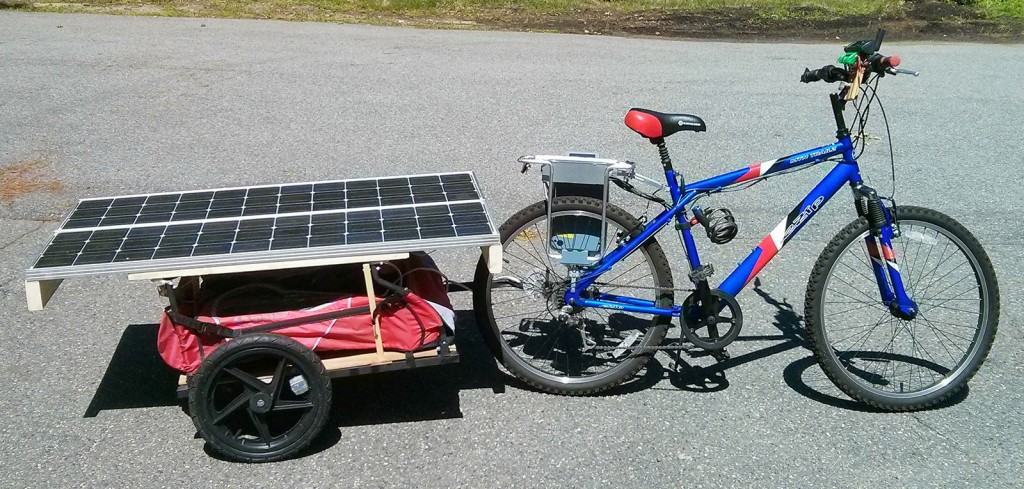
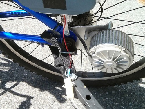
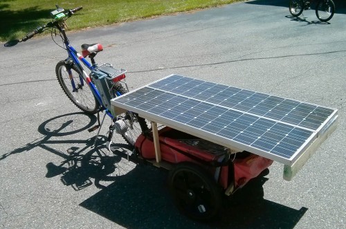
I built a solar-powered bike. It works, but not quite as well as I’d hoped.

IMG_20130806_120725 copy

I started with a 2008 Currie “E-Zip Mountain Trailz” (sic; ugh) electric bike, which works pretty well.

That is powered by a pair of 12v 10AH SLA batteries, in series for 24 volts. I’ve always been afraid to ride for long distances for fear I’d run out of power before getting home. (The thing weighs 70 pounds, and I’m no athlete, so it’s painful to go up hills without power.)

I’d been thinking of putting solar panels on it to charge the batteries while I ride. I didn’t have any appropriately-sized panels around, so I didn’t do it until this summer, when I decided to try using a bike trailer to hold the panels.

The trailer solves the problem of the panels being shaded by my body when I ride, and also avoids problems with the weight of the panel hardware messing up the balance of the bike.

I have some 20 year old Siemens SM55 modules, rated at 55 watts (new, when pointed at the sun). These things are huge and heavy – 51 x 12 inches, and 12 pounds each (1300 x 330 mm, 5.5 kg). And since the eBike runs on 24 volts, I’d need 2 panels in series to charge the battery (at least without a DC-DC boost converter). That’s 24 pounds, not counting mounting hardware.

But, hey, with a trailer, who cares how much it weighs, right? And 110 watts is a lot of power – likely enough to completely power the bike while riding (on average, on a sunny day).

So I got a used bike trailer; $50 on Craigslist:

The bike trailer as I got it

The bike trailer as I got it (nylon roof & child seat removed)

I took off some of the trailer hardware to make it easier to mount the panels, and installed a plywood floor to make a storage compartment under the panels.

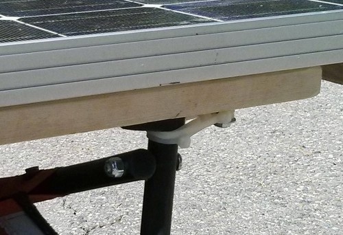
Then I used a couple of pieces of lumber to attach two panels together (at the ends), and mounted more lumber on the sides for mounting on the trailer. I cut slots to fit the trailer poles, and attached the panels to the trailer using standoffs and cable ties:

Cable tie straps hold the panels on

Cable tie straps hold the panels on

I also had to use more lumber to reinforce the trailer poles, which were only meant to hold a nylon sunshade (not 30+ pounds of panel hardware).

I was going to get a 24v charge controller to avoid putting too much voltage into the batteries, but I haven’t gotten around to that – I just wired the output of the panels (in series) parallel with the 24V battery; good enough for now.

Solar panel output wired in parallel with the battery

Solar panel output wired in parallel with the battery

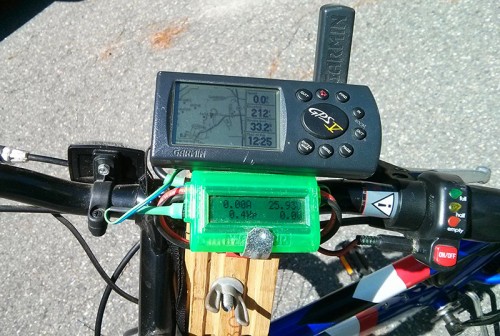
"Watts-Up" meter is just used as a voltmeter. The venerable Garmin GPS V is also powered off the 24v system.

“Watts-Up” meter is just used as a voltmeter.
The venerable Garmin GPS V is also powered off the 24v system.

Finally, I made a bumper sticker to go on the back of the panel; it reads “CAUTION – HIGH CURRENT STAND BACK 500 MM” (just visible in the last picture below, if you zoom in). I figured that would keep the ignorant from messing with the bike (and it fits my skewed sense of humor).

So, how does it work?

It works. Mostly, sort of. As long as I’m riding in full sunlight I can go indefinitely if the road is level or not too steep.

I tried a test run riding to work – about 12 miles – on a sunny day.

I weigh nearly 220 pounds, the bike is 70 pounds, and the trailer with the panels is something like another 50 pounds. So the whole setup is maybe 350 pounds. That’s too much for the motor to pull up a steep hill without a lot of help from me.

I got to work OK and not too tired, in about 90 minutes (about 8.2 mph average – not at all impressive by road bicyclist standards). I did have to work my way up hills.

At work I got delayed and ended up going home close to dusk. I started out riding in the shade. Halfway home, I had a dead, dead battery and about 7 miles still to go. And 350 pounds to drag up each hill. After mighty struggles, I gave up and called for a ride home.

A week or so later, I tried the same trip on a light steel street bicycle (about 20 pounds, with narrow smooth tires and no suspension – in other words, efficient).

I got to work again in about the same time, only slightly more tired than with the electric bike. With the vastly lighter and more efficient bike, going up hills with that was no harder than with the solar bike (with the motor helping). And I was able to get home with no problem.

In the end, a simple street bike turned out to be just as fast, not much more effort to ride, and way more practical – it even works in the shade.

But it was fun to try.

CAUTION- HIGH CURRENT. STAND BACK 500 MM

CAUTION- HIGH CURRENT STAND BACK 500 MM

Idea: Waterproof RV roofs with air pressure

Here’s another idea I don’t want to bother patenting.

I’ve owned 2 motorhomes so far, and the roofs always leak. There are lots of holes in the roof for vents, wires, etc., and with all the jostling a motorhome gets on the road, after a while lots of invisibly small cracks open up (despite sealant) and the roof leaks – even if you apply more sealant every year.

Make the roof a hollow structure with air pressure inside. It could be a flexible inflatable structure, or rigid but with a hollow air-tight space inside.

Then pressurize the inside of the roof with air from a pump or tank.

When tiny gaps appear in the roof, the air will escape outward (being replaced by the pump or tank) and will push away water, instead of letting it in. So the interior will stay dry.

The pressure doesn’t have to be high – a few PSI (tens of kPA) should be enough to prevent water from coming inside.

How often the pump runs (or the tank empties) is a measure of how many leaks there are in the roof – when there are enough to bother with, you go and apply sealant. When the leak stops, you’ve found the spot.

You could even pump in colored smoke to help find leaks.

This would be a cheap solution – a molded (or inflatable) roof doesn’t cost much and a $20 electric air pump are all you need.