It’s been quite a while since I posted an update on my GPS-steered parachute for recovery of rockets. This is is the first in a series of posts where I’ll try to bring things up to date.
(For those who want way-too-much-dry-detail, my Flight Test Notes updated thru August 2011 are here; by the time you read this, there might be a newer version linked from the main project page.)
The bottom line is that, as of this writing (August 2011), it’s not working yet, but I think I’m very close. I seem to have have been sidetracked for a whole year by using a very small baseline (horizontal distance between the left and right parachute control lines) to steer the parachute. My flight #28 in July 2010 seemed to work OK with a tiny baseline (just 2.5 inches), so for the past year all my flights have used small baselines – and none of them have steered very well (altho some worked a little bit). Only in July 2011 did I realize the small baseline was causing most of my problems – the steering lines simply get twisted together, preventing steering.
I’ll get to how I figured that out, and what I plan to do about it, in future posts.
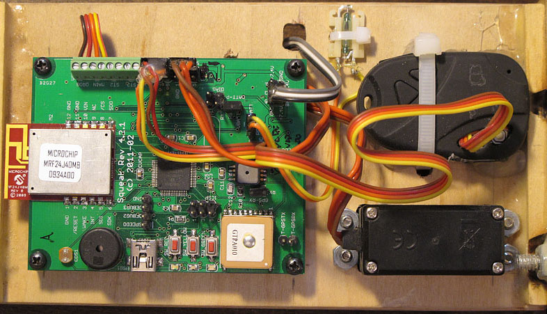
Current hardware – Rev 4.2.1 PCB
Here’s a picture of the hardware I’m flying now – I call it “Rev 4.2.1”:
It’s a slightly-updated version of the Rev 4.1 board I posted earlier:
- A Microchip PIC32 MCU (PIC32MX440, with the USB interface),
- GlobalTop PA6B GPS (updates at up to 10 Hz),
- Microchip MRF24J40MB IEEE 802.15.4 radio transceiver for telemetry,
- Freescale MP3H6115A pressure sensor for the altimeter,
- Some buttons, LEDs, and a piezo beeper,
- A USB port that right now is only used to power the board on the test bench,
- Some MOSFET switches to drive four pyro outputs (on the back side; not visible)
- Logic power is 3.3v from a Microchip TC105 switching DC-DC converter (also on the back side) – this is much more efficient than my old LDO design – the board can now sit on the pad for hours without me worrying about the battery dying.
I layout the board in Eagle PCB and have them made in China by BatchPCB.com, then populate the boards myself by hand with a soldering iron, heat gun, stereo microscope, and patience.
It runs off 6 to 9 volts; normally I use two LiIon cellphone batteries in series (see next pic) or 6 NiMH cells in series.
At this moment I have a very slightly updated version (Rev 4.2.2) out at BatchPCB being made, but I’m aiming for a new version this winter which will, I hope, run off a single LiIon cell (3.6 v) and have a charging circuit on board, so it’ll charge off the USB port.
Also visible in the picture is the back side of the steering servo, and the 808 keychain camera I’ve written about before. This looks upward at the parachute in flight, and has proved extremely useful in diagnosing what is going on with the parachute and steering (see videos linked in the Flight Test Notes).
Note the little glass-bulb thing at the top between the PCB and the camera. This is a magnetic reed switch, and it’s how I turn on the board inside the rocket without making a hole in the rocket for a switch. Unlike a Hall effect sensor, the reed switch doesn’t draw any power at all. I hold a magnet on the outside of the rocket, opposite the reed switch. The switch closes while the magnet is there, which powers up the CPU. As soon as the CPU boots, it pulls up an output line to keep the power on, even after the magnet is removed.
I can turn the power off with the reed switch too (the CPU monitors the switch as an input), but these days I usually power down with a telemetry command – when the CPU gets the command, it drops the same output line and turns itself off.
Electronics sled
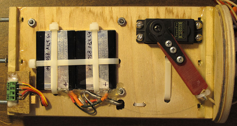
Below is a picture of the back side of the e-sled, with the batteries and servo top visible.
A few lessons I learned the hard way:
- Pot wires with hot glue, not epoxy. Potting is important to keep wires from flexing and eventually breaking, but epoxy is brittle – the wire will flex exactly where the epoxy ends. Hot glue dries rubbery, so it allows some gentle flexing but spreads the load out along the wire. It’s easier to remove if you have to, too.
- Modify cellphone LiIon cells before using them in another application. Cellphone LiIon cells have a protection circuit – usually a tiny PCB mounted at the connector – which limits charge and discharge current for the battery. Lithium batteries can catch fire (or theoretically even explode) if improperly charged or damaged – these circuits are supposed to prevent some of that, but the circuit can turn off the battery just at the critical moment when you need maximum current from it (it happened). So rip those boards out and connect directly to the cell. (And take proper precautions in general.)
- Note the screw terminal connector at the end of the payload bay. This position lets me connect up the ejection charges without having to remove the whole e-sled and use long wires – my next spin of the PCB will mount the screw terminals on the end of the board directly, so I don’ t have to remotely position them this way.

