Archive for category Rockets

Rev3 rocket electronics part 5: stateMachine.c

This is post #5 in a series covering the hardware and software design for my work-in-progress GPS-guided rocket recovery project. The main index to the series of posts is here, and an introduction to the project (a PowerPoint presentation) is here.

In this post I’ll cover stateMachine.c, which implements the finite state machine (FSM) that handles most of the functional logic of the system.

STATE MACHINE

When implementing a state machine, I don’t feel an obligation to observe the constraints of a formal FSM of the kind taught in schools, where all functionality happens in state transitions.

Instead, I treat each state as a system mode. There are state entry actions and state exit actions, but while in each state the system also has a distinct behavior. While I could draw a state diagram, I’ve never bothered – the system is simple enough that it’s unnecessary, and the diagram wouldn’t capture much of the important behavior of the system.

The state machine is run one step by a call to StateMachine() from main(), which happens once each time through the main loop.

Each of the six states, IDLE, ARMED, TIMEDLAUNCH, FLIGHT, FULL, and TEST, (all defined in stateMachine.h) has an associated “state function” that implements the system behavior for that state. Each state also has an associated entry function, which can be called by state functions to cause the system to transition to a new state.

The state functions take and return no parameters and have the same names as the state symbols, but in lowercase:

  • void idle(void);
  • void armed(void);
  • void timedlaunch(void);
  • void flight(void);
  • void full(void);
  • void test(void);

The entry functions also take and return no parameters and are named based on the state they enter:

  • void enterIDLE(void);
  • void enterARMED(void);
  • etc.

The current state and sub-state are stored in global variables State and Substate.

STATE TRANSITIONS

When conditions warrant, a state function will cause a transition to a different state by calling the appropriate entry function, which will change the global variables State and Substate to reflect the new state, as well as performing any entry actions needed to configure the system for the new state.

A flag, stateTransitionInProgress, is reset to FALSE on entry into StateMachine(). Each entry function starts by verifying that this flag is FALSE, and if so, setting it TRUE. If the flag is not FALSE on entry, this indicates that the FSM has already transitioned to a new state, and therefore the call to the entry routine is invalid. In that case, the entry routine is aborted and the state remains unchanged.

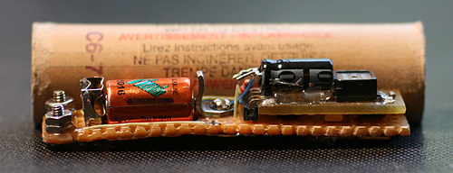
Wiring to camera shutter button

This eliminates the possibility of a subtle bug which could occur if, once a state function calls an entry function (to transition to a new state), later logic in the same state function tries to put the system into a different new Read the rest of this entry »

Rev3 rocket electronics part 4: main.c

This is post #4 in a series covering the hardware and software design for my work-in-progress GPS-guided rocket recovery project. The main index to the series of posts is here, and an introduction to the project (a PowerPoint presentation) is here.

This post covers main.c, which has just one function in it, main(), the program that runs on power-up or reset.

INITIALIZATION

main() starts by calling SetupHardware() in hardware.c, which initializes the PIC internal registers. Many of the values used to initialize things are computed from macros based on tweaks.h. OSCCON is set to control the CPU clock frequency, INTCON and PIE are set to enable the global, peripheral, UART, and Timer1 interrupts. SetupHardware() has comments on how Timer1 is used to generate the servo control pulses, which I won’t repeat here, but see my discussion of this in my posting about the ISR.

Next 16-bit timers Timer1 and Timer3 are initialized to run at a rate of 250 kHz (1/32 of the 8 MHz CPU clock) and started.

Then, the I/O ports are setup (direction and weak pullups on Port B), CVRef is setup to produce a reference voltage and an analog comparator is configured for level-conversion of the incoming received GPS data (see the hardware description for details of that) and an ADC is setup to read AN1 for the pressure sensor.

Finally Timer2 (TMR2) and CCP2 are setup to produce the 47 kHz square wave modulation for the camera control IR pulses (again, see the hardware description). Finally, the magnetic compass is initialized, if the compilation switch COMPASS is defined (it isn’t, now).

main() then turns on all 3 LEDs (to indicate that the system is powered up and running), sets the servo to the middle position, initializes the leaky integrator values used to smooth out pressure sensor readings, calls InitGPS() to send GPS commands to set the desired baud rate and mode (38,400 bps, $GPRMC and $GPGGA messages only), and initializes the state machine.

The last thing main() does before entering the main (endless) software loop is:

nextRTC8 = RTC8 + LOOP_PERIOD;

This deserves some explanation, as I use this technique a lot (mostly in stateMachine.c – see next post).

Global 32-bit variable RTC holds a count of real-time-clock (RTC) interrupts since power-up. Macros RTC24, RTC16, and RTC8 (all in globals.h) return the low-order 24, 16, and 8 bits of this count (respectively – note that the C18 compiler supports 24 bit wide variables).

This statement assigns the modulo-256 (8 bit) sum of the lower 8 bits of this count (RTC8) and a constant called LOOP_PERIOD to an 8-bit variable called nextRTC8.

LOOP_PERIOD is defined in tweaks.h as the number of RTC ticks in 40 milliseconds (25 Hz). So nextRTC8 represents the future value RTC8 will have 40 milliseconds from now.

By comparing nextRTC8 to RTC8, we can easily determine whether the 40 milliseconds have expired. Macros YET8(), YET16(), YET24(), YET32() and NOTYET8(), NOTYET16(), NOTYET24() and NOYET32() (all in globals.h) implement this comparison and allow for the possibility that by the time the comparison is made (between nextRTC8 and RTC8), RTC8 might have already moved on to a later value (if the check isn’t performed between each tick of the RTC interrupt).

So, when later in main() we say:

while (NOTYET8(nextRTC8))

we will continue in the while() loop as long as the current time has not yet reached future time “nextRTC8” (40 milliseconds from the time we set the value of nextRTC8).

Of course, nextRTC8 and RTC8 are only 8 bits wide, so the time represented in nextRTC8 had better not be more than 127 RTC ticks in the future (127 mS). If you need to deal with longer time periods than that, you’ll have to use one of the wider versions – RTC16, RTC24, or RTC32.

MAIN LOOP

The main loop of the program starts with while(1) and runs once every 40 milliseconds (25 Hz). All system functions are driven by this loop, except what the interrupt service routine (ISR) does.

A 32-bit variable CycleCount is incremented each time through.

Graph from logged pressure altitude & GPS data. GPS altitude is useless – data is heavily damped, resulting in a lag of 12 seconds or so. But the GPS position data is not too bad.

GPS

Then CheckForNewGPSFix() is called (from nmeaGps.c).  Any incoming data from the GPS has been received by the ISR and placed in a small text buffer, NMEAbuffer[]. CheckForNewGPSFix() looks at the text buffer to see if a complete message has been received from the GPS. If so, it parses the message. ($GPGGA or $GPRMC; these are the only two messages that are handled.) Read the rest of this entry »

Rev3 rocket electronics part 3: Source code summary

This is post #3 in a series covering the hardware and software design for my work-in-progress GPS-guided rocket recovery project. The main index to the series of posts is here, and an introduction to the project (a PowerPoint presentation) is here.

This post is an introduction to the source code. (Which can be downloaded from my last post.)

OVERVIEW OF SOURCE FILES

The software consists of the following C source files:

  • main.c – hardware init and main program loop
  • stateMachine.c – finite state machine (most functionality is here)
  • globals.c – global variables
  • isr.c – interrupt service routine
  • hardware.c – hardware abstraction wrappers
  • peripherals.c – higher-level (than hardware.c) peripheral control
  • nmeaGps.c – reads and parses NMEA-0183 standard format GPS data
  • logging.c – logging of flight status data to Flash memory
  • compass.c – drives Honeywell HM55B magnetic compass (no longer used)

and the following header files:

  • tweaks.h – main “tweakable” parameter file and compilation switches
  • stateMachine.h – defines state values and prototypes for stateMachine.c
  • globals.h – prototypes for globals.c, generally useful macros
  • hardware.h – symbol definitions for hardware abstractions, prototypes for hardware.c
  • peripherals.h – peripheral-related macros and constants, prototypes for peripherals.c
  • nmeaGps.h – data structure for GPS fixes, prototypes for nmeaGps.c and related constants
  • logging.h – data structures for flight data logging, prototypes for logging.c
  • compass.h – hardware abstractions for compass, prototypes for compass.c
  • debug.h – macros to support “Z-80 Speedometer”
  • djllib.h – variable type definitions, standard constants, misc. macros

In addition there is the Microchip header file pic18f26k20.h and the linker file 18f2620i.lkr. Neither of these are my work – they are unmodified from Microchip.

Servo arrangement after successful radio-controlled landing. To fit in the rocket, the servo arm stays at an extreme setting until after parachute deployment.

SYMBOL NAMING CONVENTIONS

These are the naming conventions I use for function and variable names:

Function scope Variable scope Convention 1st character
n/a Block (local) lower_case_ABBR_excepted_underscore_delimited Lowercase
File (normal) File mixedCaseDelimitedABBRexcepted Lowercase
Global (exported) Global MixedCaseDelimitedABBRexcepted Uppercase
Macro Macro ALL_CAPS_UNDERSCORE_DELIMITED Uppercase
n/a Typedef ALL_CAPS_UNDERSCORE_DELIMITED Uppercase

Also, a name with a leading underscore, for example _name(), indicates a “hidden” function or variable which is not meant for general use. Usually it’s a component of some other function that is meant to be used on a normal basis. (See __waitloop_internal() in hardware.c and #define wait() in hardware.h for an example.)

WHERE TO START

If you want to have a look at the software with an eye to modifying it, I suggest you start with a quick skim of the following files (in this order): Read the rest of this entry »

Rev3 rocket electronics part 2: Software overview

This is post #2 in a series covering the hardware and software design for my work-in-progress GPS-guided rocket recovery project. The main index to the series of posts is here, and an introduction to the project (a PowerPoint presentation) is here.

This post will introduce the software at a high level.

I’ll start with a rough outline of the software architecture and functional spec for the Rev3 hardware/software system.

I say rough because, like most one-man projects, things evolve without necessarily being thoroughly documented. That said, the code is heavily commented (and the comments are up-to-date), so it shouldn’t be too difficult to follow what is going on.

This post will give you an idea of what to expect, but you really need to read the source code to fully understand what is going on.

Regarding rights: My attitude toward the software is a little different than for the hardware. I’m posting all the source code and these comments to help people understand it, and I want to encourage people to use and modify it. However, much hard-won experience is represented in the software and it has a lot more general utility, even outside of rocketry.

So here’s the deal – I hereby grant everyone and everything in the universe permission to use and modify this software for any NON-COMMERCIAL purpose whatsoever, PROVIDED that you (a) agree not to sue me about it, (b) credit Nerdfever.com as the original source of the software in any publications, and (c) agree that I make no promises and that if you’re unhappy the most I owe you is what you paid me (zip, zero, nada, nothing). Oh, and you agree to USE THIS AT YOUR OWN RISK, that you’re a responsible adult and know that rockets can be dangerous and hurt people if you’re not careful (regardless of whether or not software is involved) so you’ll be careful and will not blame anyone else if you screw up (especially me).

I’ll be very pleased if you leave a comment or drop me an email if you find it useful, but you don’t have to.

For COMMERCIAL use, ask my permission first.  If you’re going to make lots of money off my work, I’d like a (oh-so small and reasonable) cut.  But I’ve no intention of giving anybody heartache over small amounts – just ask, I think you’ll find me surprisingly easy to deal with.

That said, here is the the code, including the Microchip MPLAB IDE project files, just as it appears in the project folder: Rev3Board.zip

You may find it handy to look at the code when reading this introduction, although I’ll save the gory details for later posts.

SOFTWARE ARCHITECTURE

There is no real-time operating system (RTOS) – no operating system of any kind.

All the code is in C running directly on the “naked” hardware. In my experience RTOSes are very rarely useful in simple-to-moderate complexity embedded systems. Instead, they tend to add a needless layer of complexity and overhead that serves to obscure what is really going on. (RTOSes do have a proper place, I just think they’re over-used.)

I also don’t use any of Microchip’s hardware interface libraries. Instead, I control the hardware directly according to the PIC datasheet. I prefer to know and control what is really going on, and learning how to control the hardware doesn’t take much longer than learning how to use the library functions.

Some will say this makes the code less portable to other MCUs, but I prefer to have a solid understanding of what the code is doing so that I can intelligently port it when needed. In my view this is less risky than relying on the compatibility of “black-box” libraries which, in my experience, often disappoint. I do isolate all the hardware interface functions in a single module (see hardware.h and hardware.c).

As you read the code, you’ll see that I compute many constant values in the C pre-processor. (For example, see #define FLASH_BUFFER_ROWS and #define MS_TO_UTICKS  in hardware.h.)  I find this helps clarify how the constants are calculated, as well as reducing code size.

CONDITIONAL COMPILATION (#ifdef)

I make some use of conditional compilation in the code. The major compilation switches are all set (or not) in file tweaks.h. Most of them relate to the presence or absence of various bits of hardware (magnetic compass, GPS models, particular servos, etc.)

The compilation flags __DEBUG and ICD2 disable the “red” button input (symbol SW_RED) for debug builds. This button shares a pin with the ICD2 reset line, so including __DEBUG will include the compilation switch ICD2, which prevents the “red” button from being used (and therefore resetting the CPU). When these switches are defined, the compiler will generate a couple of warnings about code that doesn’t do anything – this is intentional. Read the rest of this entry »

Rev3 rocket electronics part 1: Hardware

This is post #1 in a series covering the hardware and software design for my work-in-progress GPS-guided rocket recovery project. The main index to the series of posts is here, and an introduction to the project (a PowerPoint presentation) is here.

In this post I’ll cover the hardware design, including the schematic, board layout, and Eagle PCB files from my “Rev3” hardware of March 2007. (That’s the most recent version I have working as of this writing.)  This post is also a good starting point even if you’re mainly interested in the software – as a tightly integrated system, an understanding of the hardware is key to the software as well.

About rights: I hereby grant everyone and everything in the universe permission to use and modify this hardware design for any purpose whatsoever. In exchange, you agree not to sue me about it. I make no promises. By using the design you agree that if you’re unhappy the most I owe you is what you paid me (zip).  That seems fair.

If you find this useful, I’ll be pleased if you drop me a note or leave a comment here (just so I know it’s been helpful to someone) and if you give credit to Nerdfever.com for the design in any publications. But you don’t have to.

The board was designed in Eagle PCB, which is available in a free “light” edition, limited to non-profit use and 2-layer boards of not more than 4.0 x 3.2 inches. (Sufficient for this board.) Eagle takes some getting used to, but works well.

If you want to modify my design, here are the Eagle PCB files for the schematic and board: Autopilot_r3.zip

This hardware has made many successful flights, and supports the following features:

  • PIC18F2620 MCU (programmable in C)
  • GPS interface
  • Drives a hobby servo (to steer the parachute)
  • Pressure altimeter (good to about 2 feet precision)
  • Triggers parachute deployment at apogee
  • Able to log flight data in flash memory
  • Drives an in-flight digital camera
  • Piezo speaker output
  • 3 push-buttons, 3 LEDs

Figure 1 shows the schematic:

Rev3 Schematic

Fig. 1 - Rev3 schematic

A few comments about the circuit are in order.

MCU

The MCU is a PIC18LF2620. It has 3968 bytes of RAM and 64 kbytes of Flash memory, which is available for both program space and logging of flight data. It will run at up to 8 MHz off the PIC’s internal oscillator – I don’t use an external crystal.

Interestingly, these specs are very similar to those of the Apollo Guidance Computer. Except that the PIC is a single 28-pin chip, costs about $4, and draws only a couple of milliamps.

You can program the PIC using Microchip’s free C18 compiler and free MPLAB IDE environment – those are what I recommend.

GPS

The board was designed to interface with a GlobalSat EM-406 GPS using a serial UART interface. I’ve used others (see tweaks.h for a list); it will probably work fine with any serial-interface GPS.

The PIC transmits to the GPS on pin 17 of the PIC (TX).

Note that pins 4 and 5 of the PIC are tied together, and pin 6 (C1OUT)  is tied to pin 18 (RX). This is part of a no-hardware level-shifting scheme that allows the 5v PIC to read data from the EM-406 GPS, which outputs at 0v/2.85v. Read the rest of this entry »

GPS rocket update, PIC32 pinout spreadsheet

The 2009 rocket flying season is nearly over, and I haven’t had a single flight all year toward my GPS-guided rocket recovery project. I’ve been too busy with business stuff to work on it, but my goal for this winter is to get the new “Rev4” PCB up and running, ready for flight in the spring.

For that, I’ve decided to shift from the PIC18 to the MIPS-based PIC32 parts.

Which means I’ll be porting over a lot of code from the PIC18, so now seems a good time to post my long-promised source code and schematics for what I’ve done so far, which I plan to do in the coming days.

For now, here is a Excel spreadsheet with the PIC32 pinout for the 64 pin TQFP parts. Each time I do a MCU-based design, I make a table like this for allocating MCU pins by function. If you’re working with the PIC32, you may find it useful for the same purpose.

Click the image to download the .XLS file.

PIC32MXx40 pinout

PIC32MXx40 pinout

Tiny Rocket Altimeter Fits In 18mm Motor Casing

I just finished building this tiny rocket altimeter.  It fits inside a standard 18mm (diameter) rocket motor case – in this case, a used Estes C6-7 motor.

side_img_0376

It’s based on Robert DeHate’s PICO-AD4 altimeter.  It measures peak altitude and will fire the ejection system at either apogee or a main deployment point (a few hundred feet AGL).

The most difficult thing was finding an adequate battery that would fit – I ended up with a L1016 6v alkaline; they are widely available (online) and inexpensive.   It uses a 220 uF capacitor to fire a AG1 flashbulb for deployment (220 uF is enough to do this reliably).

Here’s the schematic – not much to it:

ad4-altimeter-schematic_500px

I drew a power switch, but I couldn’t get it to fit.  So I just take out the battery to turn it off.

I made the hole for the battery with a Dremel tool.

Here’s the back side:

bottom_img_0379

The jumper on the back (J1) selects whether the ejection will happen at apogee or using the main deployment point.

The two bolts/nuts on the end are the attachment for the AG1 bulb (2-56 hardware), the battery clips were made from parts in my junk box.  The negative terminal is soldered onto two cut-off pieces of paperclip (paperclips are made out of good-quality steel), which are in turn soldered onto the perfboard.

(By the way, I’ve discovered the perfect tool for cutting PCB traces – a little battery-powered engraver. Harbor Freight sells the one I use for less than $10.  Just make sure you blow away all the tiny copper pieces afterward with canned air.)

The resistor is just to limit the charging current on the capacitor – that little battery really doesn’t like high currents.  The resistor value is not critical – anything from 500 to 3000 ohms or so should be fine.

Here’s a top view (with it running and the LED blinking):

top_img_0366

The 220 uF cap is held in place with some hot glue (as are some of the wire-wrap wires on the back).  I used epoxy to hold down the jumper, screws and base nuts and to reinforce the thin bits of perfboard next to the battery – otherwise the whole thing bends too much under the off-axis tension from the battery springs (I broke an earlier version that way).

Here it is snug in it’s 18mm motor case:

end_img_0362

The flashbulb wires are meant to go out the other end, thru the rocket nozzle hole.

As you can see, I had to ream out the inside of the motor case a bit to get things to fit.  (This was desirable anyway, to get out all the black soot left after firing – do NOT try this with a unused motor!!)

The reaming was done starting with a 1/2″ drill bit, then a 9/16″, finishing with sandpaper wrapped around the 9/16″ bit (use some double-stick tape to keep it on there).  It helps a lot to have a drill press.

I haven’t flown it yet, but it works well on the workbench.

Big, Bad Black Rock

or,

How I Learned to Stop Worrying and Love … Dust


This is my NEMROC presentation from 2007; about my trip to the Black Rock Desert (Nevada) in September 2007 for the XPRS rocket launch.

Two friends and I (plus the son of one of my friends) drove from Boston to Black Rock in 51 hours, in my 20 year old RV.

The Black Rock Desert is simply … otherworldly.  I love it, but it’s not to everyone’s taste.

There are over 120 slides (mostly pictures) in the PowerPoint file – the images in this post are just a sample.

I’m quite happy with the way most of the photos came out; particularly the ones taken at night.  The Black Rock has really dark night skies – the Milky Way can easily be seen most nights, and came out well in the photos.

The last evening we had a night launch with lights mounted on the rockets, as you can see here.

Night launch

Night launch

I hope to go again the the fall of 2009; if you’re a New England rocketeer and are interested in coming along (and splitting the gas cost – the RV gets 7 mpg), leave a comment.

Click on the link below to download the full set of PowerPoint slides (15 MBytes).

2007-11-big-bad-black-rock.ppt

Interim Report: GPS-guided Rocket Recovery

Saturn Zero

or,

Nevada Dave and the Rocket-Eating Trees

This is my presentation for NARCON 2010 (was NEMROC 2008 … see below), summarizing my efforts over the last three years since 2006 toward building a model rocket that won’t get lost.

The idea is that it carries a GPS and a steerable parachute, so it steers itself back to the launch pad on the way down.

An introduction to the project is in the PowerPoint presentation below.  Fair warning: It’s 60 Mbytes.

Update January 2010: I’ve posted all the hardware design and source code for the “Rev 3” hardware on this site.   The main index to the series of posts is here.

Update March 2010: I’ve replaced the presentation with a slightly updated version that I presented at NARCON 2010.  It discusses a little about the “Rev 4” hardware, based on the 32-bit PIC32 MCU, toward the end. Download all 3 files (and put them in the same folder) if you want the Google Earth links to work.

2010-03 NARCON Presentation.ppt (PowerPoint file)

1004_f2_pressure.kml (Google Earth .KML file, flight of 2008-10-04)

1101f2_pressure.kml (Google Earth .KML file, flight of 2008-11-01)

If PowerPoint is an issue, here’s a PDF version of the slides (15 MB):

2010-03 NARCON Presentation.pdf (PDF)

New, improved rocket tracks in Google Earth

I’ve been working on the routine that converts my logged GPS and altimeter data into Google Earth .KML files.

It’s a lot nicer looking now – below is the same flight I posted on July 19 2008, but re-converted with the new routine.

New, improved Google Earth snapshot

New, improved Google Earth snapshot

Black marks pre-flight data, green marks ascent, yellow marks apogee (actually 1.5 seconds of data starting with apogee) and red marks descent.  The lighter “whitish” marks are the GPS fixes, in this case 1.0 seconds apart.  All the data in between is from the altimeter (25 Hz samples), with interpolated lat/lon position.

Here’s the .KML file – it’s fun to load it into Google Earth and fly around the track.

You can see where the rocket electronics detected launch (where black turns to green) and where it detected apogee and ejected the parachute (where green turns to yellow) – the crazy below-the-ground data point is the overpressure (sensed by the altimeter) from the ejection charge.

Last, if you click on the pad icon, you’ll see all kinds of flight data, automatically calculated from the log by the new routine.

It’s rather ugly MATLAB/SCILAB code.  Someday I’ll post the source code online (once I clean it up a bit).  If you’re desperate, drop me a note and I’ll email it to you.